|
|
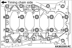
1.Removal the all bearing cap bolt.
|
|
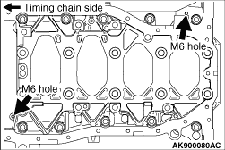
2.Insert the M6 bolts into the 2 places shown in the illustration to remove the lower
crank case.
|
|
|
When temporarily placing the crankshaft with the crankshaft sensing ring attached, temporarily
place it on a V-block to prevent the teeth of the sensing ring from deforming.
|
|
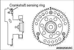
1.Temporarily tighten all bolts.
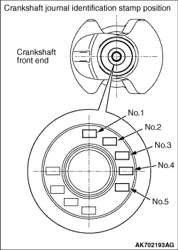
2.Tighten crankshaft sensing ring bolts to the torque of 11 ± 1 N·m
in the tightening order shown in the illustration.
|
|
|
1.Install the thrust bearing at the No. 3 bearing on the cylinder block side. Application
of engine oil makes the installation easy.
|
|
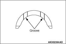
2.Install the thrust bearing with the grooved side toward the crankshaft weight side.
|
|
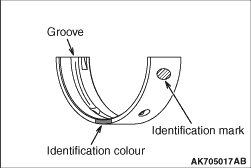
1.When replacing the crankshaft bearing upper, select the bearing with the size corresponding
to the cylinder block journal diameter in the table below.
|
|
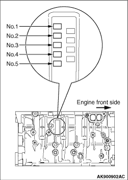
2.The crankshaft bearing upper has the identification mark at the illustrated position.
3.Install the selected crankshaft bearing upper.
Cylinder block
|
Crankshaft bearing
|
Identification mark
|
Hole inside diameter mm
|
Identification mark or colour
|
1
|
64.000 - 64.006
|
1 or Black
|
2
|
64.006 - 64.012
|
2 or None (purple)
|
3
|
64.012 - 64.018
|
3 or Green
|
|
|
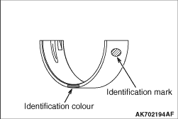
1.When replacing the crankshaft bearing lower, select the bearing with the size corresponding
to the crankshaft journal diameter in the table below.
|
|
2.The crankshaft bearing lower has the identification mark at the illustrated position.
3.Install the selected crankshaft bearing lower.
Crankshaft
|
Crankshaft bearing
|
Identification mark
|
Journal diameter mm
|
Identification mark or colour
|
0
|
59.985 - 59.988
|
0 or Red (Pink)
|
1
|
59.982 - 59.985
|
1 or Black
|
2
|
59.979 - 59.982
|
2 or None (purple)
|
3
|
59.976 - 59.979
|
3 or Green
|
4
|
59.973 - 59.976
|
4 or Blue
|
|
|
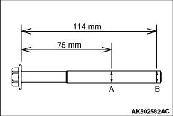
1.Before reusing the bearing cap bolt (M11), check according to the following procedures.
(1)
Measure the 2 points on the outside diameter of thread as shown in the illustration.
(2)
When the difference between the measured outside diameters is beyond the limit value,
replace the bearing cap bolt (M11).
Limit value: 0.15 mm
2.Completely remove the liquid gasket adhering to the cylinder block and lower crank
case to remove the grease.
| caution |
Install the lower crank case within 3 minutes of applying the
liquid gasket.
|
3.Apply the bead of 2.5 ± 0.5 mm liquid gasket to the lower crank case shown
in the illustration.
Specified sealant:
Three bond 1217G or equivalent
4.Apply the engine oil to the threaded portion and the seat surface of the bolt.
|
|
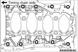
5.Tighten the bearing cap bolt (M11) to the specified torque of 65 ± 2 N·m
according to the tightening order.
|
|
6.
| caution |
- When the tightening angle
is smaller than the specified tightening angle, the appropriate tightening capacity cannot be
secured.
- When the tightening angle is larger than the specified tightening angle, remove
the bolt to start from the beginning again according to the procedure.
|
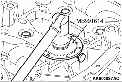
Use Special tool Angle gauge (MB991614) to tighten the bearing cap bolt (M11) to the torque
of 120° to 125°.
|
|
7.Tighten the bearing cap bolt (M8) to the specified torque of 26 ± 6 N·m
according to the tightening order.
|
|
8.After installing the bearing cap bolts, check the crankshaft axial play. If the axial
play exceeds the limit, replace the thrust bearing.
Standard value: 0.05 - 0.25 mm
Limit: 0.3 mm
|
)

)
)
)
)
)
)
)
)
)
)
)
)
)