|
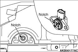
Aligning the notch of the valve lift control shaft with that of the valve lift sensor,
install the valve lift sensor to the rocker shaft holder C. Tighten them with the bolts to the
specified tightening torque of 2.8 ± 0.8 N·m.
|
|
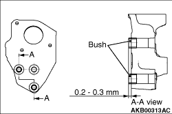
1.Install the bush to the motor bracket as shown in the illustration.
2.Install the motor bracket with the bush to the cylinder head.
|
|
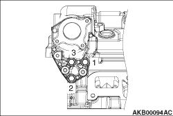
3.According to the sequence shown in the illustration, install the motor bracket. Tighten
them with the bolts to the specified tightening torque of 21 ± 5 N·m.
|
|
1.
| caution |
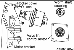
- When installing the valve lift control motor, pay attention
to the oil seal not to be damaged.
- If the oil seal is damaged, replace it.
|
Apply a small amount of engine oil to the oil seal lip of the rocker cover.
|
|
2.
| caution |
- When rotating the coupling, do not apply the torque more
than 3 N·m to prevent the damage.
- If the oil seal is damaged, replace it.
|
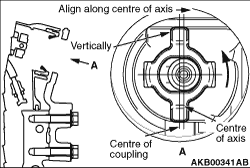
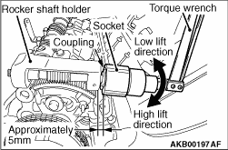
To get the easy caulking to the valve lift control motor, rotate the worm shaft coupling
anti-clockwise. Place it to the position as shown in the illustration.
| note |
Align the coupling centre with the axis centre. When manually rotating the coupling, insert
a 12-point socket (24 mm) into the position approximately 5mm away from the rocker shaft holder.
Connect the mini torque wrench and slowly rotate them.
|
|
|
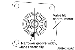
3.Place the valve lift control motor coupling to the position as shown in the illustration.
4.
| caution |
- Do not forcibly insert
the valve lift control motor.
- If the valve lift control motor is not inserted, check again the direction of the
valve lift control motor coupling, and the deviation from the worm shaft coupling centre.
|
Until the clearance from the motor bracket’s mating face becomes 0 mm, manually
insert the motor.
|
)

)
)
)
)
)
)
)