|
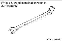
| note |
Use the recommended tool f/head & o/end combination wrench
(MB992699) to remove the EGR valve mounting bolt shown in the figure.
|
|
|
|
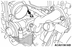
1.Insert the glow plug into the cylinder head. Rotate them 2 or 3 times by hand to temporarily
install them. Use the wrench and temporarily tighten them.
|
|
|
2.To the specified torque of 18 ± 2 N·m, tighten the glow plug that
is temporarily tightened.
|
|
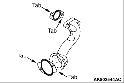
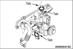
1.Temporarily install the EGR pipe "A" and the EGR pipe gasket to the EGR valve. Put the
EGR pipe gasket tab to the position shown in the illustration.
|
|
2.Put the EGR valve gasket tab to the position shown in the illustration.
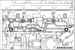
3.Install the temporarily tightened EGR pipe A and the EGR valve to the cylinder head
and the EGR cooler. Check that there is no clearance among each component. Temporarily tighten
the bolts, 1, 4 and 6, as shown in the illustration.
Temporary tightening torque: 1.3 ± 0.7 N·m
4.To the specified torque, tighten each bolt in the order shown in the illustration.
Specified torque: 20 ± 2 N·m
|
|
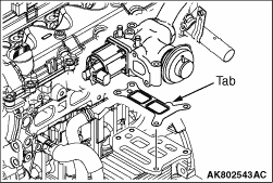
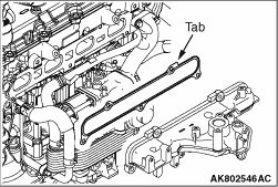
Put the inlet manifold gasket tab to the position shown in the illustration. Install the
inlet manifold gasket to the cylinder head.
|
|
|
1.Check the vacuum outlet port for clogging, and clean it if necessary.
|
|
|
2.Temporarily install the inlet manifold to the cylinder head.
|
|
3.In accordance with the order shown in the illustration, tighten the inlet manifold bolts
and nuts to the specified torque of 20 ± 2 N·m.
|
|
1.Put the EGR pipe gasket tab to the position shown in the illustration.
2.Install the temporarily tightened EGR pipe B to the EGR valve and the inlet manifold.
Check that there is no clearance among each component.
Temporary tightening torque: 1.3 ± 0.7 N·m
3.Install the tightened EGR pipe B to the specified torque.
Specified torque: 20 ± 2 N·m
|
|
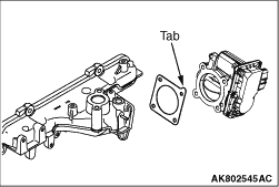
Put the throttle body gasket tab to the position shown in the illustration to install
the inlet manifold.
|
)

)
)
)
)
)
)
)
)
)