|
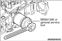
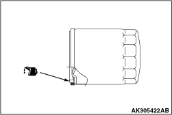
1.Use Special tool Oil filter wrench (MB991396) to remove the oil filter.
|
|
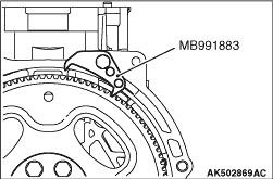
1.Use special tool Flywheel stopper (MB991883) to secure the flywheel.
2.Remove the flywheel.
|
|
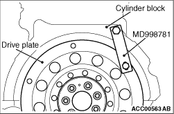
1.Use special tool Flywheel stopper (MD998781) to secure the drive plate.
2.Remove the drive plate.
|
|
|
1.Remove oil pan tightening bolts.
|
|
2.
| caution |
Lightly tap the oil pan FIPG cutter without damaging the lower crank case
and oil pan sealed area, and drive the oil pan FIPG cutter into.
|
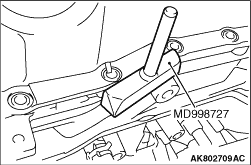
Lightly tap Special tool Oil pan FIPG cutter (MD998727) to drive in it to the illustrated
groove of the oil pan and lower crank case.
|
|
3.Use a hammer to lightly tap and slide Special tool Oil pan FIPG cutter (MD998727). Remove
the oil pan.
|
|
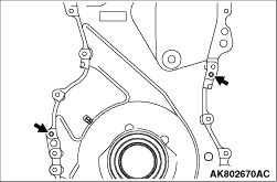
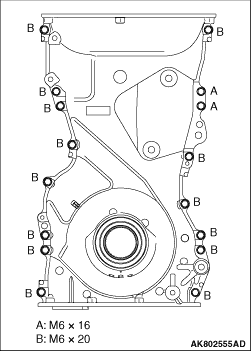
1.Insert the M6 bolts into the 2 places shown in the illustration to remove the timing chain
case.
|
|
|
1.Completely remove liquid gasket adhering to the timing chain case, cylinder block
and cylinder head to remove the grease.
|
|
|
2.
| caution |
Install the timing chain case within 3 minutes of applying the
liquid gasket.
|
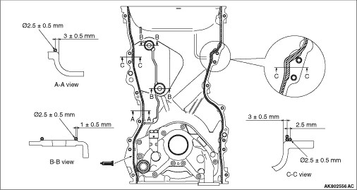
Apply liquid gasket of 2.5 ± 0.5 mm in thickness to the timing chain case. For
Cross Section C-C shown in the illustration, apply the liquid gasket in thickness of 2.5 ± 0.5
mm again.
Specified sealant:
Three bond 1217G or equivalent
|
|
3.Completely remove the liquid gasket remaining on the gasket which is the three-plane mating
surface between the cylinder head and the cylinder block to remove the grease.
4.The engine oil in the cylinder gasket oozes to the three-plane mating surface described
in Step 3. After removing the grease, swiftly apply the liquid gasket to this portion.
Specified sealant:
Three bond 1217G or equivalent
5.Install the timing chain case.
|
|
6.Tighten timing chain case mounting bolts to the specified torque of 11 ± 3 N·m.
| note |
Pay attention to the mounting bolts because they are different in length.
|
|
|
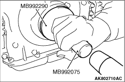
1.Apply the engine oil to the entire inner diameter of the oil seal.
2.Use the following special tools to install the front oil seal to the timing chain
case.
- Oil Seal Installer (MB992290)
- Handle (MB992075)
|
|
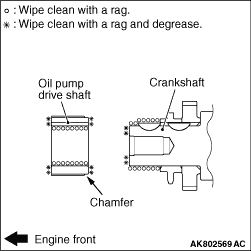
1.Install the oil pump drive shaft so that the chamfered side can face
towards the crankshaft side.
2.Use a rag to wipe off the dirt of the oil pump drive shaft and the crankshaft. Remove
the grease on the places shown in the illustration.
| note |
Remove the grease in order that adhered oil cannot decrease the friction coefficient of
the pressed area.
|
|
|
|
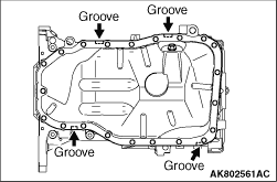
1.Completely remove the liquid gasket adhering to the lower crank case and oil pan to
remove the grease.
|
|
|
2.Apply the bead of 2.5 ± 0.5 mm liquid gasket to the oil pan shown in the
illustration.
Specified sealant:
Three bond 1217G or equivalent
|
|
|
3.Tighten the oil pan to the specified torque of 11 ± 3 N·m.
|
|
|
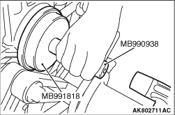
1.Apply the engine oil to the entire inner diameter of the oil seal.
|
|
2.Use the following special tools to install the rear oil seal to the cylinder block.
- Oil Seal Installer (MB991818)
- Installer Bar (MB990938)
|
|
1.If the drive plate bolt is reused, apply the sealant to the portion shown in the illustration.
Specified sealant:
Three bond 1324 or equivalent
Apply the engine oil to the flywheel thread portion and the crankshaft thread hole.
|
|
2.Use Special tool Flywheel stopper (MD998781) to fix the drive plate.
|
|
3.Tighten the drive plate bolts to the specified torque in the order shown in the illustration.
Tightening torque: 40 N·m
4.Tighten the drive plate bolts to the specified torque again in the order shown in
the illustration.
Tightening torque: 130 N·m
|
|
1.If the flywheel bolt is reused, apply the sealant to the portion shown in the illustration.
Specified sealant:
Three bond 1324 or equivalent
Apply the engine oil to the flywheel thread portion and the crankshaft thread hole.
|
|
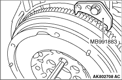
2.Use Special tool Flywheel stopper (MB991883) to fix the flywheel.
|
|
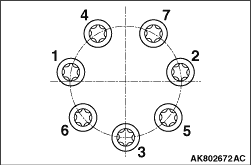
3.Tighten the flywheel bolts to the torque of 40 ± 2 N·m in the order
shown in the illustration.
|
|
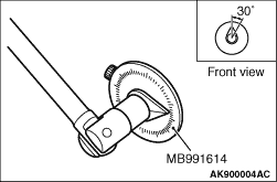
4.Use Special tool Angle sensor (MB991614) to tighten the flywheel bolts an additional 30° in
the order shown in the illustration.
|
|
|
1.Completely remove the liquid gasket adhering to the rocker cover, the timing chain
case and the cylinder head to remove the grease.
|
|
|
2.Appropriately use a minimum amount of sealant. Do not allow the sealant to go beyond
the application range.
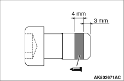
Apply the bead of 4 mm liquid gasket to the front portion shown in the illustration. Apply
the bead of 8 mm liquid gasket to the rear portion shown in the illustration.
Specified sealant:
Three bond 1217G or equivalent
|
|
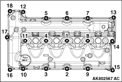
3.4.Tighten the bolts to the tightening torque of 3.0 ± 1.0 N·m in the
order shown in the illustration.
5.Next, tighten the bolts to the specified torque of 5.5 ± 0.5 N·m
in the same order.
|
|
|
1.Clean the oil filter mounting surface of the lower crank case.
|
|
2.Apply the engine oil to the O-ring of the oil filter.
|
|
| caution |
Use Special tool Filter wrench (MB991396) to install the
oil filter. Tightening it by hand causes oil leakage due to lack of torque.
|
3.Screw in the oil filter. When the O-ring contacts the mounting surface, use a filter
wrench to tighten it one turns (14 ± 2 N·m).
|
)

)
)
)
)
)
)
)
)
)
)
)
)
)
)
)
)
)
)
)
)