|
| caution |
Loosing the installation bolts for the camshaft bearing cap at
the same time causes the valve spring force, which makes the installation bolts jump out, resulting
in the damaged threads. Gradually loosen them four or five times, not in one time.
|
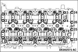
Remove the installation bolts of each camshaft bearing cap in the order
shown in the illustration.
|
|
|
Apply oil to the entire coupling to install the coupling to the slit portion
of the exhaust camshaft rear end.
|
|
|
1.Install the exhaust camshaft.
|
|
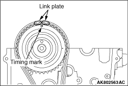
2.Align the timing chain link plate with the timing mark of the exhaust
camshaft to loop the timing chain.
|
|
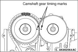
3.Install the inlet camshaft, Align the timing marks on each camshaft gear
to install them.
|
|
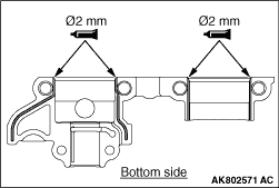
1.Apply the liquid gasket to the rear camshaft bearing cap, as shown in the illustration.
Specified sealant:
Three bond 1217G or equivalent
2.Install each camshaft bearing cap to the cylinder head.
| note |
Check the identification codes regarding the cap No. Check whether it is for the inlet
side or the exhaust side.
|
Identification mark (stamped on each camshaft bearing
cap)
I: Inlet side
E: Exhaust side
3.Install a new O- ring to the oil pipe.
4.Install the oil pipe to the camshaft bearing cap.
5.Tighten the camshaft bearing cap bolts to the specified torque in the order shown
in the illustration.
Specified torque
M6: 11 ± 1 N·m
M8: 20 ± 1 N·m
|
)

)
)
)
)
)