|
| caution |
- Do not allow sealant to
squeeze out to the screw tip.
- Do not tighten, exceeding the specified torque.
|
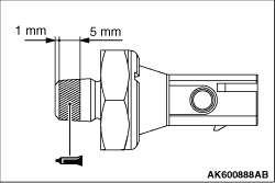
1.Completely remove sealant adhering to the oil pressure switch and cylinder block threaded
holes.
2.Apply sealant of 5 mm to the threaded portion of the oil pressure switch shown in
the illustration.
Specified sealant:
ThreeBond 1212D, ThreeBond 1215 or equivalent
3.Tighten the oil pressure switch to the cylinder block to the specified torque of 10 ± 2
N·m.
|
|
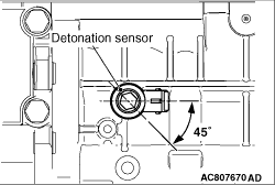
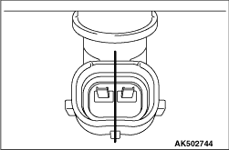
Align the detonation sensor connector with the position shown in the illustration, and
then tighten it to the specified torque of 20 ± 2 N·m.
|
|
|
Install the inlet manifold and temporarily tighten bolts.
|
|
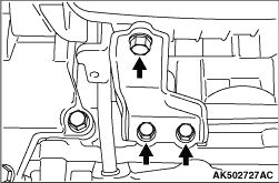
Make sure that the inlet manifold stay is in intimate contact with the inlet manifold
and cylinder block boss before tightening it to the specified torque of 20 ± 2 N·m.
|
|
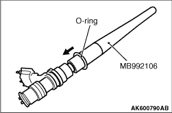
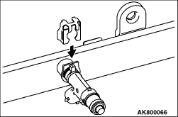
When inserting an O-ring into the injector on the injection nozzle side, use special tool
O-ring installer (MB992106) to gradually expand the O-ring, and fit it in place.
|
|
|
1.Apply gasoline to the O-ring of the injector.
|
|
|
2.Insert the injector into the delivery pipe while rotating the injector from side to
side, taking care not to damage the O-ring.
|
|
|
3.Check that the injector rotates smoothly. If it does not rotate smoothly, the O-ring
may be caught. Remove the injector and check the O-ring for damage. Then, insert it again into the
delivery pipe and check.
|
|
4.Make sure that the protrusion of the injector is at the centre as shown in the illustration.
|
|
5.Securely assemble the injector to the injector groove and delivery pipe collar.
|
|
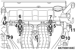
1.Install the delivery pipe assembly, bracket and injector protector on the cylinder head.
2.Tighten mounting bolts together with temporarily tightened inlet manifold mounting
bolts in the order shown in the illustration.
3.Tighten the delivery pipe assembly, bracket, injector protector rear and inlet manifold
in the order shown in the illustration.
Temporarily torque: 3.5 ± 1.5 N·m
Specified torque: 20 ± 2 N·m
|
)

)
)
)
)
)
)
)