|
|
Tighten the crank angle sensor to the specified torque of 9.5 ± 2.5 N·m.
|
|
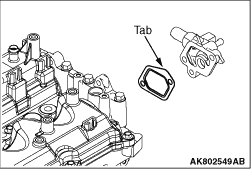
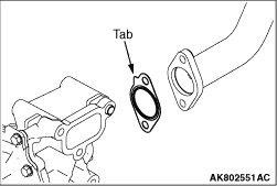
Put the water by-pass fitting gasket tab in the position shown in the illustration to
install the water bypass fitting gasket.
|
|
| caution |
- Do not allow the sealant
to run into the thread end.
- Do not tighten the oil pressure switch to the more torque than the specified torque.
|
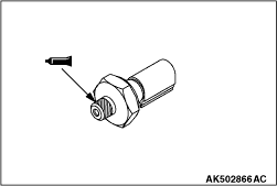
1.Sufficiently remove the sealant attached to the oil pressure switch and the cylinder
block threaded hole.
2.Apply the sealant of 5 mm to the threaded portion of the oil pressure switch as shown
in the illustration.
Sealant
ThreeBond 1215, ThreeBond 1212D or equivalent
3.Tighten the oil pressure switch to the specified torque of 19 ± 3 N·m
together with the oil cooler fitting.
|
|
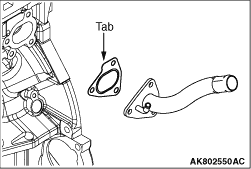
Put the water outlet fitting gasket tab in the position shown in the illustration
to install the water outlet fitting gasket.
|
|
1.
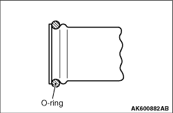
| caution |
Never use grease such as engine oil to the o-ring.
|
Apply water to replace the o-ring and easily install the new one.
2.Straightly insert the radiator lower pipe into the water inlet fitting.
|
|
1.Put the water inlet pipe gasket tab in the position shown in the illustration to install
the water pump assembly, the water pump gasket, the water inlet pipe and the gasket.
|
|
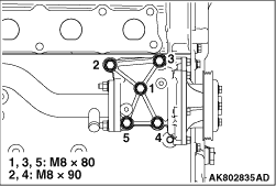
2.Install the water pump gasket and the water pump assembly to the cylinder. Tighten them
to the specified torque of 24 ± 3 N·m in the order shown in the illustration.
| note |
Pay attention to the installation bolts because they are different in length.
|
|
|
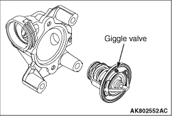
Install the thermostat with the jiggle valve facing almost straight upwards.
|
|
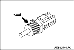
1.Apply an appropriate and minimum amount of sealant to the coolant temperature sensor,
not allowing the sealant to go beyond the specified range.
Specified sealant:
LOCTITE 262, Three bond 1324N or equivalent
2.Tighten the coolant temperature sensor to the cylinder block to the specified torque
of 30 ± 9 N·m.
|
)

)
)
)
)
)
)
)
)
)