|
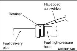
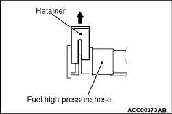
1.Follow the steps below to unlock the fuel high-pressure hose connector.
(1)
Insert a flat-tipped screwdriver (6 mm wide and 1 mm thick) into the retainer of the fuel
high-pressure hose connector.
(2)
|
|
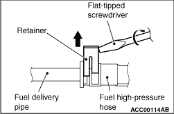
| caution |
When pushing up the retainer of the fuel high-pressure hose
connector, pay attention to avoid damage to the retainer.
|
|
Turn the flat-tipped screwdriver inserted into the retainer by 90° to push up
the retainer and unlock the fuel high-pressure hose connector.
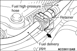
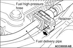
2.Remove the fuel high-pressure hose.
|
|
|
Remove the fuel delivery pipe with the fuel injectors attached to it.
|
|
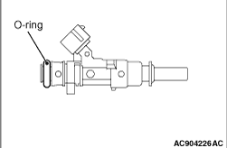
1.Apply a small amount of petrol to the O-ring.
2.While turning the fuel injector to right and left, install the O-ring to the fuel
injector with care to avoid damage to the O-ring.
|
|
|
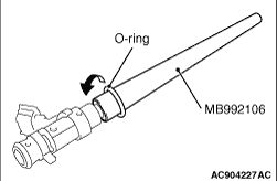
1.Apply a small amount of petrol oil to the O-ring.
|
|
2.Using special tool O-ring installer (MB992106), install the fuel injector paying attention
to avoid damage to the O-ring.
|
|
|
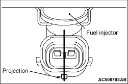
1.Apply a small amount of petrol to the O-ring.
|
|
2.Turning the fuel injector assembly to right and left, install it to the fuel delivery
pipe with care not to damage the O-ring. After the installation, check for its smooth rotation.
At this time, check that the projection part of the fuel injector assembly is in the centre.
3.If the rotation is not smooth, the O-ring may be caught. Remove the fuel injector
assembly and check the O-ring for damage. After this, re-insert it to the fuel delivery pipe
and check for its smooth rotation.
|
|
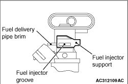
Install the fuel injector support to the fuel injector groove and fuel delivery pipe brim,
and fix the fuel injector assembly and fuel delivery pipe.
|
|
|
1.Apply a small amount of petrol to the O-ring at the end of fuel injector assembly.
|
|
|
2.
| caution |
When installing the fuel delivery pipe and fuel injector assembly
to the inlet manifold, pay attention to avoid damage to the O-ring at the end of the fuel injector assembly.
|
Install the fuel delivery pipe and fuel injector assembly to the inlet manifold.
|
|
|
3.Install the bracket and injector protector rear.
|
|
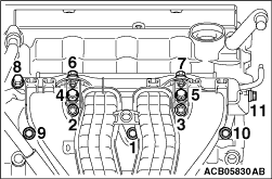
4.Loosen the inlet manifold mounting bolts and nuts (Bolts and nuts 1, 2, 3 and 9 shown
in the figure).
5.Loosen the inlet manifold stay mounting bolts (Refer to GROUP 15 - Inlet
Manifold  ). ).
6.Temporarily tighten the mounting bolts and nuts of the inlet manifold, bracket, fuel
delivery pipe and injector protector rear to the specified torque in the order of number shown
in the figure.
Tightening torque: 3.5 ± 1.5 N·m
7.Tighten the mounting bolts of the fuel delivery pipe, and the mounting bolts and nuts
of the bracket, injector protector rear and inlet manifold to the specified torque in the order
of number shown in the figure.
Tightening torque: 20 ± 2 N·m
8.Tighten the inlet manifold stay mounting bolts to the specified torque (Refer to GROUP
15 - Inlet Manifold ).
Tightening torque: 20 ± 2 N·m
|
|
1.Pull up the retainer of fuel high-pressure hose to unlock before installing.
|
|
2.Install the fuel high-pressure hose to the fuel delivery pipe.
3.
| caution |
- When pushing in the
retainer of the fuel high-pressure hose connector, pay attention to avoid damage to the retainer.
- After the installation of the fuel high-pressure hose, slightly pull the fuel high-pressure
hose to check that it is connected securely. At this time, also check that there is approximately
1 mm play.
|
Push in the retainer of the fuel high-pressure hose connector to lock the fuel high-pressure
hose and fuel delivery pipe.
|
)
)
)
)
)
)
)
)
)
)
)