|
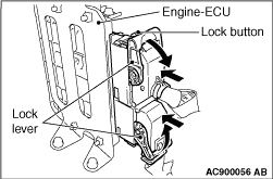
Press the lock button to unlock the lock lever. While pressing the connector cover against
the engine-ECU, turn the lock lever to the vertical position. Then, disconnect the connector from
the engine-ECU.
|
|
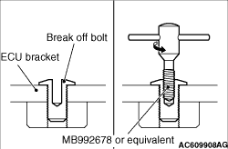
1.<Recommended tool screw extractor set (MB992678) or equivalent>
(1)
Drill in the break off bolt a hole deep enough for the tap to stand.
(2)
Use the recommended tool screw extractor set (MB992678) or equivalent to remove the
break off bolt.
|
|
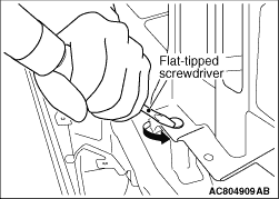
2.<When using the flat-tipped screwdriver>
(1)
Apply force towards the direction to loose the bolt by a flat-tipped screwdriver.
(2)
Remove the break off bolt.
|
|
|
Tighten the break off bolt until its head is broken off.
|
|
1.
| caution |
When inserting the connector to the engine-ECU, be careful
not to apply force in the directions other than the inserting direction.
|
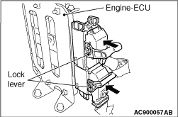
Move the lock lever of the connector to the unlock status, and then install the connector
to the engine-ECU. Insert the connector as far as it goes.
2.
| caution |
Make sure that the connector is inserted sufficiently
before locking it, or the lock lever may be damaged.
|
While pressing the connector toward the engine-ECU side, turn the lock lever to lock the
connector.
|
|
|
Turn the ignition switch to the "ON" position and then to "LOCK" (OFF)
position and hold it for at least 10 seconds.
|
 ).
).)
)
)
)
)
)