|
| caution |
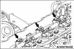
If the harness bracket is pulled or pried off forcibly, the locker cover side insert may
be damaged.
|
|
|
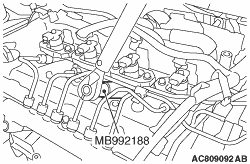
Using the special tool fuel injection pipe wrench (MB992188), remove the fuel injector
assembly side of fuel injection pipe No. 3 and No. 4.
|
|
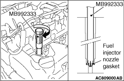
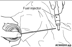
1.Insert the special tool nozzle gasket remover (MB992333) to the fuel injector mounting
hole on the cylinder head.
2.Rotate the dial of the tool as shown, and then pull out the tool while holding the
fuel injector nozzle gasket.
|
|
1.Clean the fuel injector assembly (nozzle) and the cylinder head (fuel injector insertion
hole) by following the procedure below.
(1)
|
|
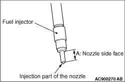
| caution |
Do not clean the injection part of the nozzle with a
resin spatula.
|
|
Using a resin spatula, scrape off the carbon deposit on the fuel injector nozzle side
face ("A" shown in the figure).
(2)
Spray the carburettor cleaner (MZ100139) or equivalent to the nozzle side face ("A" shown
in the figure).
(3)
|
|
| caution |
Do not touch the injection part of the nozzle with hand
or wipe it with a rag.
|
|
Leave the injection part for a while until the carbon deposit melts down, and then blow
air to the injection part.
(4)
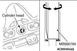
Insert the special tool ornament remover (MB990784) to the cylinder head (fuel injector
insertion hole) with turning the special tool as shown, and scrape off the carbon deposit.
(5)
|
|
| caution |
In order to prevent carbon from adhering to the inner surface
of the cylinder, blow air with the piston in the TDC position.
|
|
Remove the special tool MB990784, and blow off the carbon deposit on the cylinder head
(fuel injector insertion hole) by air.
(6)
Check that there is no carbon deposit remaining on the contact surface of the fuel
injector nozzle gasket.
|
|
| note |
Repeat step 4 to step 6 several times until the carbon deposit is completely removed.
|
|
2.Replace the fuel injector nozzle gasket with a new one.
3.
| caution |
- If the removed fuel
injector assembly to be reinstalled cannot be identified, register the injector identification code
and perform the small injection quantity learning. (Refer to GROUP 00 -
Precautions
before Service, What the Common Rail Engine Learns
 ). ).
- Securely insert the fuel injector assembly.
|
Install the fuel injector assembly.
4.Apply an adequate and minimum amount of engine oil to the thread of the fuel injector
holder mounting bolts, the lower area of the flange, and fuel injector washer.
|
|
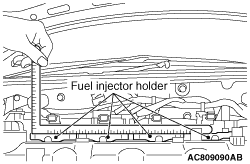
5.Install the fuel injector holder through the injector connector part, and let both right
and left sides of the fuel injector holder mounting bolts be seated at the same time. Make sure
that the fuel injector holder is placed within 2 mm in the horizontal axis by using a L-shaped
steel scale.
6.Mount the fuel injection pipe No. 1 to No. 4 and temporarily install them.
7.Tighten the bolt on the engine front side of the fuel injector holder mounting bolts
to 1.1 ±
0.1 N·m.
|
|
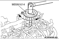
8.Use the special tool angle gauge (MB991614) to tighten the engine rear side bolts of the
fuel injector holder to 180°
±
1°.
9.Use the special tool (MB991614) to tighten the engine front side bolts of the fuel
injector holder to 90°
±
1°.
10.
| caution |
- The removed fuel injection pipe can be reassembled
up to five times. To count the number of fuel injection pipe reassembly, record it by adding
the reassembly number of this time (once usually) to the previous number of reassembly written
on the maintenance handbook. When the number of the previous reassembly reaches 5 or when the
fuel injector assembly or common rail assembly is replaced, always use a new fuel injection pipe.
At that time, write "New (0 times)" in the maintenance handbook.
- If a fuel leak is present in the fuel injection pipe and fuel injection pipe set
once, do not reuse it and replace with a new one.
- If the fuel injector assembly, common rail assembly or supply pump assembly is replaced,
the contact surface (seal surface) between the fuel injection pipe and fuel injection pipe set,
and the other side component is changed, do not reuse the fuel injection pipe and fuel supply
pump pipe and replace with a new one.
- When reassembling the fuel injection pipe, remove the foreign material attached
on the sealing surface, and install it with the contacting point of the pipe aligned.
|
Loosen the flare nut of the common rail assembly, fuel injection pipe set A, fuel injection
pipe set B, and fuel return pipe. (Refer to .)
11.Align the fuel injection pipe centre axis with the other side components (common rail
assembly and fuel injector assembly) centre axis to install the fuel injection pipe. Then, tighten
the flare nut temporarily until the tip of pipe (seal surface) contacts with the other side
components.
| note |
When the fuel injection pipe is installed, tighten the flare nut while shaking the pipe
lightly to align the centre axis of both components.
|
|
|
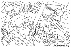
12.Using the special tool crowfoot wrench (MB992211), tighten the common rail assembly side
of the fuel injection pipe No.1 to No.4 to the temporary tightening torque calculated by the
following formula.
Tightening torque: (18 ±
2) ×
{L ÷
(L +
25)}
N·m
18 ±
2: Tightening torque of the fuel injection
pipe (unit: N·m)
L: Distance between the centre of a torque wrench drive and of its handle (unit:
mm)
25: Length of pitch for special tool between holes (unit: mm)
|
|
13.Using the special tool fuel injection pipe wrench (MB992188), tighten the fuel injector
assembly side of fuel injection pipe No. 3 and No. 4 to the temporary tightening torque.
Tightening torque: 18 ±
2 N·m
14.Using the special tool MB992211, tighten the common rail assembly side of the fuel
injection pipe No.1 to No.4 to the specified torque calculated by the following formula.
Tightening torque: (35 ±
5) ×
{L ÷
(L +
25)}
N·m
35 ±
5: Tightening torque of the fuel injection
pipe (unit: N·m)
L: Distance between the centre of a torque wrench drive and of its handle (unit:
mm)
25: Length of pitch for special tool between holes (unit: mm)
15.Using the special tool MB992188, tighten the fuel injector assembly side of the fuel
injection pipe No. 3 and No. 4 to the specified torque.
Tightening torque: 35 ±
5 N·m
16.Tighten the common rail assembly, fuel injection pipe set A, fuel injection pipe set
B, and fuel return pipe. (Refer to .)
17.Check that no fuel is leaked from the fuel injection pipe connection area and the
gasket.
|
)
)
)
)
)
)
)
)
)
)