|
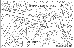
Using the special tool fuel injection pipe wrench (MB992188), remove the supply pump side
of fuel injection pipe set A and B.
|
|
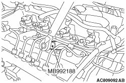
Using the special tool fuel injection pipe wrench (MB992188), remove the fuel injector
assembly side of fuel injection pipe No. 3 and No. 4.
|
|
| caution |
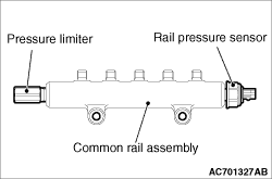
- When operating, do not support the common rail assembly by holding the rail
pressure limiter and the pressure sensor at both ends.
- Before the installation, make sure that there is no foreign object or rust to the
thread and to the high-pressure pipe sheet surface.
|
|
|
|
1.Install the common rail assembly to the cylinder head, and let the mounting bolt be
seated. (until the bolt slightly touches the common rail installation surface)
|
|
|
2.Mount the fuel injection pipe No. 1 to No. 4 and temporarily install them.
|
|
|
3.Mount the fuel injection pipe set B and temporarily install it.
|
|
|
4.
| caution |
- The removed fuel injection pipe can be reassembled
up to five times. To count the number of fuel injection pipe reassembly, record it by adding
the reassembly number of this time (once usually) to the previous number of reassembly written
on the maintenance handbook. When the number of the previous reassembly reaches 5 or when the
fuel injector assembly or common rail assembly is replaced, always use a new fuel injection pipe.
At that time, write "New (0 times)" in the maintenance handbook.
- If a fuel leak is present in the fuel injection pipe and fuel injection pipe set
once, do not reuse it and replace with a new one.
- If the fuel injector assembly, common rail assembly or supply pump assembly is replaced,
the contact surface (seal surface) between the fuel injection pipe and fuel injection pipe set,
and the other side component is changed, do not reuse the fuel injection pipe and fuel supply
pump pipe and replace with a new one.
- When reassembling the fuel injection pipe, remove the foreign material attached
on the sealing surface, and install it with the contacting point of the pipe aligned.
|
Align the fuel injection pipe centre axis with the other side components (common rail
assembly, fuel injector assembly and supply pump assembly) centre axis to install the fuel injection
pipe. Then, tighten the flare nut temporarily until the tip of pipe (seal surface) contacts
with the other side components.
| note |
When the fuel injection pipe is installed, tighten the flare nut while shaking the pipe
lightly to align the centre axis of both components.
|
|
|
5.Using the special tool crowfoot wrench (MB992211), tighten the common rail assembly side
of the fuel injection pipe No.1 to No.4 and fuel injection pipe set B to the temporary tightening
torque calculated by the following formula.
Tightening torque: (18 ± 2) × {L ÷ (L + 25)} N·m
18 ± 2: Tightening torque of the fuel injection
pipe (unit: N·m)
L: Distance between the centre of a torque wrench drive and of its handle (unit:
mm)
25: Length of pitch for special tool between holes (unit: mm)
|
|
6.Using the special tool fuel injection pipe wrench (MB992188), tighten the fuel injector
assembly side of fuel injection pipe No. 3 and No. 4 and the supply pump side of fuel injection
pipe set B to the temporary tightening torque.
Tightening torque: 18 ± 2 N·m
7.Using the special tool MB992211, tighten the common rail assembly side of the fuel
injection pipe No. 1 to No. 4 and fuel injection pipe set B to the specified torque calculated
by the following formula.
Tightening torque: (35 ± 5) × {L ÷ (L + 25)} N·m
35 ± 5: Tightening torque of the fuel injection
pipe (unit: N·m)
L: Distance between the centre of a torque wrench drive and of its handle (unit:
mm)
25: Length of pitch for special tool between holes (unit: mm)
8.Using the special tool MB992188, tighten the fuel injector assembly side of the fuel
injection pipe No. 3 and No. 4 and the supply pump side of the fuel injection pipe set B to
the specified torque.
Tightening torque: 35 ± 5 N·m
9.Tighten the common rail assembly to the specified torque.
Tightening torque: 25 ± 7 N·m
10.Check that no fuel is leaked from the fuel injection pipe connection area and the
gasket.
|
|
|
1.
| caution |
- The removed fuel injection pipe can be reassembled
up to five times. To count the number of fuel injection pipe reassembly, record it by adding
the reassembly number of this time (once usually) to the previous number of reassembly written
on the maintenance handbook. When the number of the previous reassembly reaches 5 or when the
fuel injector assembly or common rail assembly is replaced, always use a new fuel injection pipe.
At that time, write "New (0 times)" in the maintenance handbook.
- If a fuel leak is present in the fuel injection pipe and fuel injection pipe set
once, do not reuse it and replace with a new one.
- If the fuel injector assembly, common rail assembly or supply pump assembly is replaced,
the contact surface (seal surface) between the fuel injection pipe and fuel injection pipe set,
and the other side component is changed, do not reuse the fuel injection pipe and fuel supply
pump pipe and replace with a new one.
- When reassembling the fuel injection pipe, remove the foreign material attached
on the sealing surface, and install it with the contacting point of the pipe aligned.
|
Align the fuel injection pipe centre axis with the other side components (common rail
assembly and supply pump assembly) centre axis to install the fuel injection pipe. Then, tighten
the flare nut temporarily until the tip of pipe (seal surface) contacts with the other side
components.
| note |
When the fuel injection pipe is installed, tighten the flare nut while shaking the pipe
lightly to align the centre axis of both components.
|
|
|
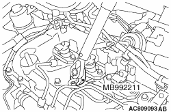
2.Using the special tool fuel injection pipe wrench (MB992188), tighten the supply pump
side of fuel injection pipe set A to the temporary tightening torque.
Tightening torque: 18 ± 2 N·m
|
|
3.Using the special tool crowfoot wrench (MB992211), tighten the common rail assembly side
of the fuel injection pipe set A to the temporary tightening torque calculated by the following
formula.
Tightening torque: (18 ± 2) × {L ÷ (L + 25)} N·m
18 ± 2: Tightening torque of the fuel injection
pipe (unit: N·m)
L: Distance between the centre of a torque wrench drive and of its handle (unit:
mm)
25: Length of pitch for special tool between holes (unit: mm)
4.Using the special tool MB992188, tighten the supply pump side of the fuel injection
pipe set A to the specified torque.
Tightening torque: 35 ± 5 N·m
5.Using the special tool MB992211, tighten the common rail assembly side of the fuel
injection pipe set A to the specified torque calculated by the following formula.
Tightening torque: (35 ± 5) × {L ÷ (L + 25)} N·m
35 ± 5: Tightening torque of the fuel injection
pipe (unit: N·m)
L: Distance between the centre of a torque wrench drive and of its handle (unit:
mm)
25: Length of pitch for special tool between holes (unit: mm)
6.Check that no fuel is leaked from the fuel injection pipe connection area.
|
 ).
).)
)
)
)
)