|
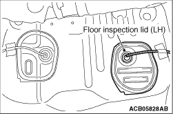
1.Remove the floor inspection lid (LH).
|
|
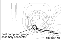
2.Disconnect the fuel pump and gauge assembly connector.
|
|
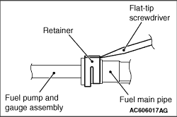
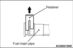
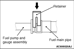
3.Insert a flat-tipped screwdriver (6 mm wide and 1 mm thick) into the retainer of the fuel
main pipe connector.
|
|
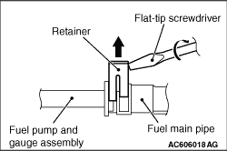
4.
| caution |
When pushing up the retainer of the fuel main pipe connector,
pay attention to avoid damage to the retainer.
|
Turn the flat-tipped screwdriver inserted into the retainer by 90 degrees to push up the
retainer and unlock the fuel main pipe connector.
5.Disconnect the fuel main pipe from the fuel pump and gauge assembly.
|
|
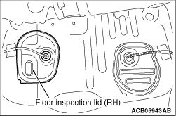
1.Remove the floor inspection lid (RH).
|
|
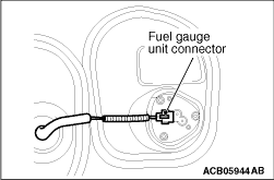
2.Disconnect the fuel gauge unit connector.
|
|
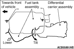
1.Remove the fuel tank, continuously checking that it does not make contact with the differential
carrier assembly.
|
|
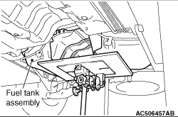
2.Hold the fuel tank assembly with the transmission jack, and remove the connecting bolts
of fuel tank band and the connecting nuts of fuel tank assembly.
3.Remove the fuel tank assembly in the tilt direction, paying attention not to bump
it against the differential carrier assembly.
|
|
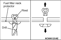
Use a drill (6.0 mm) to make a hole in the rivet to break it, and then remove the rivet.
|
|
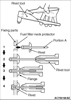
Use a rivet tool shown in the illustration to connect the parts with rivets by the following
procedures.
1.Insert the rivet into a corresponding location.
2.Set the rivet tool at a portion A of rivet.
3.While pushing the flange surface of the rivet onto parts to be fixed with the rivet
tool, press the handle of the tool.
4.Thin part of portion A of the rivet will be cut off and the part is fixed in position.
|
|
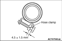
After connecting the fuel filler hose, tighten the bolts of hose clamp so that the tightening
dimension is 4.5 ± 1.5 mm.
|
|
1.Pull up the retainer of fuel main pipe to unlock before installing.
|
|
2.
| caution |
- When pushing in the
retainer of the fuel main pipe connector, pay attention to avoid damage to the retainer.
- After the installation of the fuel main pipe, slightly pull the fuel main pipe to
check that it is connected securely. At this time, also check that there is approximately 1
mm play.
|
Install the fuel main pipe to the fuel pump and gauge assembly securely and push in the
retainer of the fuel main pipe connector to lock the fuel main pipe and fuel pump and gauge
assembly.
|
 ).
).)
)
)
)
)
)
)
)
)
)
)
)
)
)