REMOVAL AND INSTALLATION


caution
  • When the catalytic converter or exhaust centre pipe (DPF) is replaced, use the M.U.T.-III to initialise the learning value (Refer to GROUP 00 - Precautions Before Service, Initialisation Procedure for Learning Value in Common Rail Engine ).
  • When the catalytic converter is replaced, perform the forcible DPF regeneration after learning value in DPF system (Refer to GROUP 17 - Emission Control <Diesel>, DPF System, Forcible DPF Regeneration ).

<2WD>


Removal steps


1.
Main muffler


2.
Gasket


·
No.1 exhaust gas temperature sensor (Refer to GROUP 17 - Diesel particulate filter (DPF) system sensors).


·
No.2 exhaust gas temperature sensor (Refer to GROUP 17 - Diesel particulate filter (DPF) system sensors ).


·
No.3 exhaust gas temperature sensor (Refer to GROUP 17 - Diesel particulate filter (DPF) system sensors ).


3.
Front exhaust pressure pipe


4.
Rear exhaust pressure pipe


5.
Exhaust centre pipe


6.
Gasket


7.
Hanger bracket assembly


8.
Catalytic converter bracket


9.
Heat cover assembly


·
Engine upper cover (Refer to GROUP 13D - Fuel Injector ).


·
Air cleaner, air Intake pipe (Refer to GROUP 15 - Air cleaner )


·
Fuel pipe (Refer to GROUP 13D - Fuel injection pump )
<<A>>

10.
Catalytic converter assembly


11.
Gasket
<<B>>
>>A<<
12.
Rivet


13.
Front floor rear heat protector


·
Rear floor under cover (Refer to GROUP 51 - Under cover ).
<<B>>
>>A<<
14.
Rivet


15.
Front floor front heat protector

<4WD>


Removal steps


1.
Main muffler


2.
Gasket


·
No.1 exhaust gas temperature sensor (Refer to GROUP 17 - Diesel particulate filter (DPF) system sensors).


·
No.2 exhaust gas temperature sensor (Refer to GROUP 17 - Diesel particulate filter (DPF) system sensors ).


·
No.3 exhaust gas temperature sensor (Refer to GROUP 17 - Diesel particulate filter (DPF) system sensors ).


3.
Front exhaust pressure pipe


4.
Rear exhaust pressure pipe


5.
Exhaust centre pipe


6.
Gasket


7.
Hanger bracket assembly


8.
Catalytic converter bracket


9.
Heat cover assembly


·
Engine upper cover (Refer to GROUP 13D - Fuel injector ).


·
Air cleaner, air intake pipe (Refer to GROUP 15 - Air cleaner )


·
Fuel pipe (Refer to GROUP 13D - Fuel injection pump )
<<A>>

10.
Catalytic converter assembly


11.
Gasket
<<B>>
>>A<<
12.
Rivet


13.
Front floor rear heat protector


·
Rear floor under cover (Refer to GROUP 51 - Under cover ).
<<B>>
>>A<<
14.
Rivet


15.
Front floor front heat protector

REMOVAL SERVICE POINT


<<A>> CATALYTIC CONVERTER ASSEMBLY REMOVAL


1.Remove the air cleaner assembly, air intake pipe, fuel pipe and heater hose.
2.
caution Remove a careful catalytic converter assembly so as not to damage a fuel filter assembly.
Remove the catalytic converter mounting nut, and pull out the catalytic converter assembly towards the upper side of the engine compartment.

<<B>> RIVET REMOVAL


caution Be careful not to damage the heat protector with the drill.

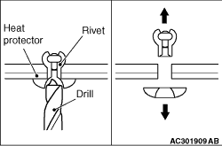
Use a drill (6.0 mm) to make a hole in the rivet to break it, and then remove the rivet.

INSTALLATION SERVICE POINT


>>A<< RIVET INSTALLATION


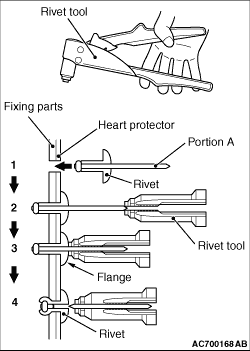
Use a rivet tool shown in the illustration to connect the parts with rivets by the following procedures.
1.Insert the rivet into a corresponding location.
2.Set the rivet tool at a portion A of rivet.
3.While pushing the flange surface of the rivet onto parts to be fixed with the rivet tool, press the handle of the tool.
4.Thin part of portion A of the rivet will be cut off and the parts is fixed in position.