|
| caution |
Do not insert the screwdriver tool deep as the stator core could be damaged.
|
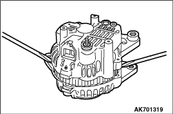
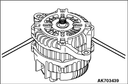
1.With a screwdriver blade inserted between the front bracket and stator
core, pry to separate the stator from the front bracket.
2.If they are hard to separate, lightly strike the bracket with a plastic hammer while
prying with the screwdriver.
|
|
| caution |
Use care not to damage the rotor.
|
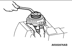
With the pulley side facing up, hold the rotor in a vice and remove the
pulley.
|
|
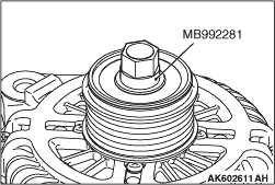
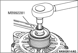
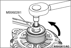
1.Set the special tool to the pulley.
Special tool
Hexagon socket (MB992281)
|
|
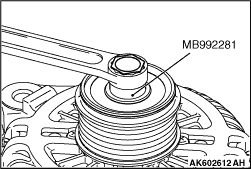
2.Set the closed wrench to the hexagonal area of the special tool.
Special tool
Hexagon socket (MB992281)
|
|
3.Insert the hexagonal bit socket having width across flats of 10 mm into the hexagonal
area of the rotor shaft.
4.Hold the pulley with the closed wrench. Rotate the rotor shaft clockwise to remove
the pulley.
|
|
| caution |
Do not insert the screwdriver blades too deep. Doing so could
damage the stator coil.
|
Insert the blades of screwdrivers between the front bracket and stator core, and pry and
separate them with the screwdrivers.
|
|
| caution |
- Use care that no undue force is exerted to lads
of diodes.
- Check that the heat from the soldering iron is not transmitted
to the diode for a long time.
|
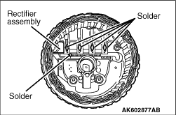
1.Use a soldering iron (180 to 250 W) to unsolder the stator. This work should complete
within approximately four seconds to prevent heat from transferring to the diode.
2.When removing the rectifier from the regulator assembly, unsoldered on the rectifier.
|
|
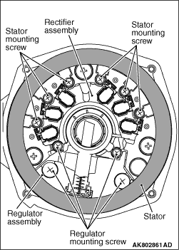
1.Remove 6 installation screws of the stator lead wire, and then remove the stator.
2.Remove 4 installation screws of the regulator to remove the regulator assembly.
|
|
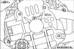
After installing the regulator assembly, insert a piece of wire through the hole in the
rear bracket while pressing the brush to keep the brush against movement.
| note |
Unless inserting the wire to fix the brush, the rotor installation is difficult.
|
|
|
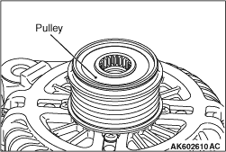
With the pulley side facing up, hold the rotor in a vice and install the
pulley.
|
|
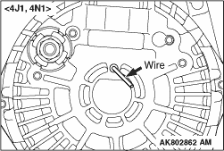
After installing the rotor, remove the wire used to secure the brush.
|
|
|
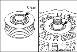
1.Clean the inner race of the front bearing and that of the pulley.
|
|
2.Screws the inner race of the pulley until it touches the inner race of the front bearing.
|
|
3.Set the special tool to the pulley.
Special tool
Hexagon socket (MB992281)
|
|
4.Set the closed wrench to the hexagonal area of the special tool.
Special tool
Hexagon socket (MB992281)
|
|
5.Insert the hexagonal bit socket having width across flats of 10 mm into the hexagonal
area of the rotor shaft.
6.Hold the pulley with the closed wrench.
Rotate the hexagonal bit socket anti-clockwise to tighten it to the specified torque of
97 ± 1 N·m.
|
)

)
)
)
)
)
)
)
)
)
)
)
)
)
)
)
)
)