|
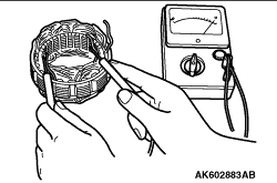
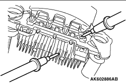
1.Check the rotor coil continuity. Make sure that there is continuity between the slip rings. Measure the rotor resistance. If it is excessively small, it indicates a shorted rotor. If there is no continuity or if it is shorted, replace the rotor assembly.
Standard value: 3 - 5 Ω
|
|
2.Check for rotor coil grounding. Make sure that there is no continuity between the slip ring and the core. Replace the rotor assembly if there is continuity.
|
|
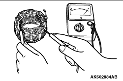
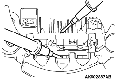
1.Check the stator continuity. Make sure that there is continuity between the coil leads. Replace the stator assembly if there is no continuity.
|
|
2.Check for coil grounding. Make sure that there is no continuity between the coil and the core. Replace the stator assembly if there is continuity.
|
|
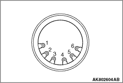
1.Check the electrical continuity between the stator coil terminals.
2.Check the electrical continuity of the points shown in the table below. Confirm that there is electrical continuity.
If there is not, replace the stator.
|
|
Terminal connector of tester
|
Electrical continuity
|
1 - 2
|
Presence of electrical continuity
|
1 - 3
|
2 - 3
|
4 - 5
|
4 - 6
|
5 - 6
|
|
|
|
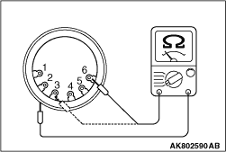
3.Check the insulation between the stator coil terminal and the coil.
4.Check the electrical continuity of the points shown in the table below. Confirm that there is not electrical continuity.
If there is, replace the stator.
|
|
Terminal connector of tester
|
Electrical continuity
|
1 - Core
|
Absence of electrical continuity
|
2 - Core
|
3 - Core
|
4 - Core
|
5 - Core
|
6 - Core
|
|
|
|
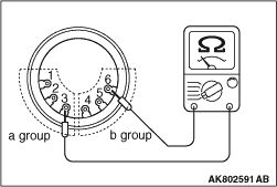
5.Check the insulation between coil terminals of each group.
6.Check the electrical continuity of the points shown in the table below. Confirm that there is not electrical continuity.
If there is, replace the stator.
|
|
Terminal connector of tester
|
Electrical continuity
|
1 - 4
|
Absence of electrical continuity
|
1 - 5
|
1 - 6
|
2 - 4
|
2 - 5
|
2 - 6
|
3 - 4
|
3 - 5
|
3 - 6
|
|
|
|
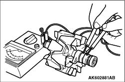
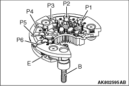
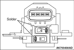
1.Positive Rectifier Test: Check for continuity between positive rectifier and stator coil lead connection terminal with a circuit tester.
If there is continuity in both directions, diode is shorted. Replace rectifier assembly.
|
|
2.Negative Rectifier Test: Check for continuity between negative rectifier and stator coil lead connection terminal.
If there is continuity in both directions, diode is shorted, and rectifier assembly must be replaced.
|
|
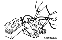
3.Diode Trio Test: Check three diodes for continuity by connecting an ammeter to both ends of each diode.
If there is no continuity in both directions, diode is faulty and heatsink assembly must be replaced.
|
|
Use the analogue type tester to make sure the electrical continuity of each diode meets the table.
Unless the electrical continuity of each diode meets the table. replace the rectifier.
|
|
(-) side
|
(+) side
|
Electrical continuity
|
E
|
P1, P2, P3, P4, P5, P6
|
Yes
|
B
|
No
|
P1, P2, P3, P4, P5, P6
|
E
|
No
|
B
|
Yes
|
|
|
|
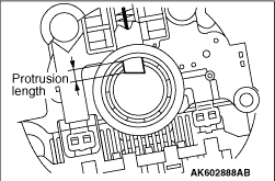
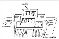
1.Replace the brush if its protrusion length is less than the limit.
Limit: min. 2 mm
|
|
2.Unsolder pigtail and remove old brush and spring.
|
|
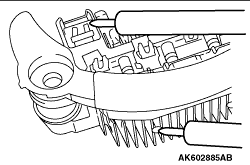
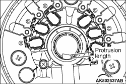
1.Measure the length of the protrusion of the brush. Replace the brush if the protrusion length is shorter than the limit.
Limit: min. 2 mm
2.Unsolder the lead of the brush. The brush will come out, becoming ready for removal.
|
|
3.Install a new brush by pushing it into the holder as shown in the drawing and soldering the lead.
|
)
)
)
)
)
)
)
)
)
)
)
)
)
)
)