|
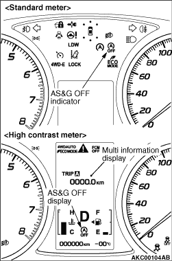
When the AS&G OFF switch is depressed, the AS&G system should be turned
"OFF" and the AS&G OFF indicator/display should be turned "ON". When the following
items in the table, related to the AS&G system, are abnormal, the AS&G OFF indicator/display
should blink. When the AS&G OFF indicator/display continues to blink, check the output
of the diagnosis code. After the ignition switch is turned "ON", the AS&G OFF indicator/display
should be turned "ON" for several seconds so that the indicator/display can be checked for the
normal operation.
| note |
When the engine-ECU, CVT-ECU or the ASC-ECU detects a diagnosis code, the AS&G
OFF indicator/display is also blinked.
|
|
|
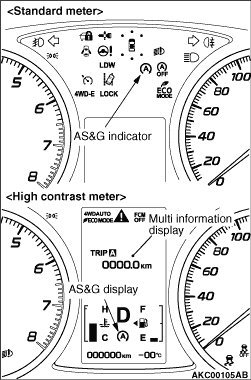
When the specified conditions are satisfied during the engine operation, the AS&G-ECU
should send engine stop request signal to the engine-ECU and the engine-ECU should stop the engine.
At that time, the AS&G indicator/display should be turned "ON". If the following items
in the table, related to the AS&G system, are applied, the AS&G indicator/display
should blink. When the AS&G indicator/display continues to blink, carry out the check
according to the applied item. After the ignition switch is turned "ON", the AS&G OFF
indicator/display should be turned "ON" for several seconds so that the indicator/display can
be checked for the normal operation.
|
|
|
Refer to GROUP 00 - How to Use Troubleshooting/Inspection Service Points - Diagnosis
Function.
|
|
|
Reading data list using M.U.T.-III enables you to check the vehicle body harnesses and
components for abnormalities. Sensor input or output to the actuator can be displayed in numerical
values or graphs in the data list.
|
|
|
DIAGNOSIS PROCEDURE
- After the ignition switch is in "LOCK" (OFF) position, connect the M.U.T.-III to
the diagnosis connector.
- Turn the ignition switch to the "ON" position.
- Select "AS&G" from System select Screen of the M.U.T.-III.
- Select "Data List" from AS&G Screen.
- Use the data list function to perform the check (Refer to
 ). ).
- If any abnormality is found, inspect and repair vehicle body harnesses and components.
- After repair, check that input and output have returned to normal.
- If a diagnosis code which is caused by inspection and repair work is generated,
erase the diagnosis code.
- Perform a test run to check that the malfunction phenomenon is resolved.
|
Code No.
|
Diagnosis item
|
Control content during malfunction
|
B1351
|
DC/DC converter (control system) performance
|
- In the normal operation, the auto stop is prohibited.
- If the malfunction is detected during the auto stop, carry out the forcible auto
start.
|
B1352
|
DC/DC converter (control system) system
|
- In the normal operation, the auto stop is prohibited.
- If the malfunction is detected during the auto stop, carry out the forcible auto
start.
|
B1353
|
DC/DC converter (control system) control circuit
|
- In the normal operation, the auto stop is prohibited.
- If the malfunction is detected during the auto stop, carry out the forcible auto
start.
|
B1355
|
AS&G functional error
|
- In the normal operation, the auto stop is prohibited.
- If the malfunction is detected during the auto stop, carry out the forcible auto
start.
|
B1356
|
DC/DC converter (control system) diag output line
|
- In the normal operation, the auto stop is prohibited.
|
C1102
|
Starter interlock circuit
|
- In the normal operation, the auto stop is prohibited.
- If the malfunction is detected during the auto stop, carry out the forcible auto
start.
|
P1612
|
Starter relay for auto start
|
- In the normal operation, the auto stop is prohibited.
- If the malfunction is detected during the auto stop, carry out the forcible auto
start.
|
U0001
|
Bus off
|
- In the normal operation, the auto stop is prohibited.
- If the malfunction is detected during the auto stop, carry out the forcible auto
start.
|
U0100
|
Engine-ECU time-out
|
- In the normal operation, the auto stop is prohibited.
- If the malfunction is detected during the auto stop, carry out the forcible auto
start.
|
U0101
|
CVT-ECU time-out
|
- In the normal operation, the auto stop is prohibited.
- If the malfunction is detected during the auto stop, carry out the forcible auto
start.
|
U0121
|
ASC-ECU time-out
|
- In the normal operation, the auto stop is prohibited.
- If the malfunction is detected during the auto stop, carry out the forcible auto
start.
|
U0126
|
Steering wheel sensor CAN time-out
|
- In the normal operation, the auto stop is prohibited.
- If the malfunction is detected during the auto stop, carry out the forcible auto
start.
|
U0131
|
EPS-ECU time-out
|
- In the normal operation, the auto stop is prohibited.
- If the malfunction is detected during the auto stop, carry out the forcible auto
start.
|
U0141
|
ETACS-ECU time-out
|
- In the normal operation, the auto stop is prohibited.
- If the malfunction is detected during the auto stop, carry out the forcible auto
start.
|
U1180
|
Combination meter time-out
|
- In the normal operation, the auto stop is prohibited.
- If the malfunction is detected during the auto stop, carry out the forcible auto
start.
|
U1210
|
Brake lamp switch status error
|
- In the normal operation, the auto stop is prohibited.
- If the malfunction is detected during the auto stop, carry out the forcible auto
start.
|
U1211
|
Engine Parity/Toggle bit error
|
- In the normal operation, the auto stop is prohibited.
- If the malfunction is detected during the auto stop, carry out the forcible auto
start.
|
U1212
|
CVT Parity/Toggle bit error
|
- In the normal operation, the auto stop is prohibited.
- If the malfunction is detected during the auto stop, carry out the forcible auto
start.
|
U1213
|
ABS/ASC Parity/Toggle bit error
|
- In the normal operation, the auto stop is prohibited.
- If the malfunction is detected during the auto stop, carry out the forcible auto
start.
|
U1214
|
ETACS Parity/Toggle bit error
|
- In the normal operation, the auto stop is prohibited.
- If the malfunction is detected during the auto stop, carry out the forcible auto
start.
|
)
)