|
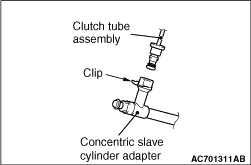
| caution |
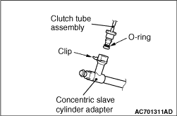
- Do not remove the O-rings and the clips from
the clutch tube and the concentric slave cylinder adapter.
- If the O-rings or the clips of the clutch tube and the concentric slave cylinder
adapter are damaged, replace each assembly.
|
|
|
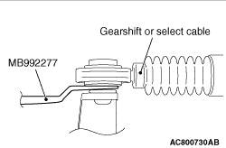
| caution |
Be careful not to pull out the cable directly to disconnect the joint because the cable
could be broken.
|
Use the clip remover (special tool: MB992277), and disconnect the joint.
|
|
|
Only loosen the bolts from the engine and transmission assembly (do not remove).
|
|
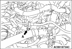
Remove the injector protector mounting bolt (A shown in the illustration).
|
|
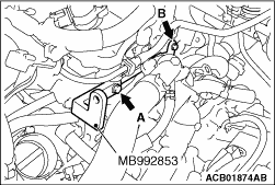
1.Tighten the engine hanger plate (special tool: MB992853) to the specified torque at A
in the figure (injector protector rear mounting bolt) and B in the figure (vacuum pipe assembly mounting
bolt).
Tightening torque: 20 ± 2 N·m (A in the figure)
Tightening torque: 11 ± 1 N·m (B in the figure)
|
|
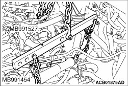
2.Assemble the engine hanger (special tool: MB991527) with the chain of the engine hanger
balancer (special tool: MB991454).
|
|
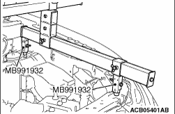
3.<When using engine hanger (special tool: MB991928)>
(1)
Assemble the engine hanger (special tool: MB991928). (Set the components
below to the base hanger.)
- Slide bracket (HI)
- Foot x 4 (standard) (MB991932)
(2)
Set the foot of the special tool as shown in the figure.
|
|
| note |
Adjust the engine hanger balance by sliding the slide bracket (HI).
|
|
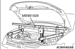
(3)
Connect the engine hanger (Special tool: MB991928) to the engine hanger (special tool:
MB991527). Remove the garage jack and then remove the transmission assembly upper part coupling
bolts that have been loosened previously.
|
|
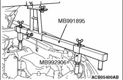
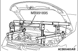
4.<When engine hanger (Special tool: MB991895) and engine hanger
attachment (Special tool: MB992906) are used>
(1)
Set the foot of engine hanger (special tool: MB991895) as shown in the figure.
|
|
| note |
Slide the front foot of engine hanger (special tool:MB991895) to balance the engine hanger.
|
|
(2)
Connect the engine hanger (Special tool: MB991895) to the engine hanger (special tool:
MB991527). Remove the garage jack and then remove the transmission assembly upper part coupling
bolts that have been loosened previously.
|
|
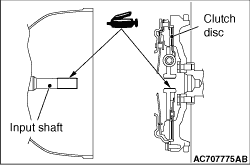
When installing the transmission assembly, apply the specified grease to the spline of
clutch disc and input shaft.
Specified grease: MITSUBISHI MOTORS GENUINE Part No.0101011 or equivalent
|
|
Tighten the injector protector rear mounting bolt (A in the figure) to the specified torque.
Tightening torque: 20 ± 2 N·m
|
|
| caution |
- Check that the O-ring and the clip are not damaged before installing the clutch tube and
the concentric slave cylinder adapter.
- If the O-ring of the clutch tube and the concentric slave cylinder adapter and their
installation positions are contaminated, clean with the clutch fluid before installation.
|
After installing the clip to the concentric slave cylinder adapter, install the clutch
tube assembly to the concentric slave cylinder adapter.
|
 ).
).)
)
)
)
)
)
)
)
)
)
)
)