|
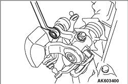
Remove the fixing nuts shown, then separate the control shift lever from the bellcrank.
|
|
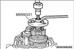
Using special tool Puller set (MB992221), remove the synchronizer clutch hub No.3.
|
|
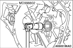
1.Using special tool Input shaft holder (MD998802), lock the input shaft.
|

|
2.Remove the flange nut from output shaft assembly.
|

|
Using special tool Rear axle bearing outer race puller (MB990801), remove the 5th drive
gear.
|
|
|
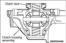
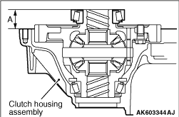
1.Set the differential assembly to the clutch housing assembly.
|
|
2.Push and fit the tapered roller bearing outer race by hand.
3.To fit the tapered roller bearing outer race, rotate the differential assembly by
hand about 10 times.
|
|
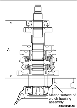
4.Put the clutch housing assembly on the surface table and use a height gauge to measure
the dimension "A" which is from the mating surface of the clutch housing assembly to the end
surface of the tapered roller bearing outer race.
|
|
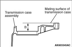
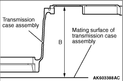
5.Put the straight edge on the mating surface of the transmission case assembly and measure
the dimension "B" with a vernier caliper.
6.Select the shim whose dimension is the difference between "B" and "A."
7.Install the differential assembly to the clutch housing assembly. Tighten the transmission
case bolts to the specified torque of 29 ± 5.8 N·m.
|
|
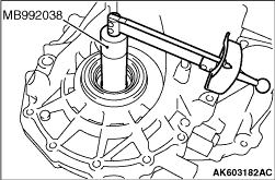
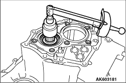
8.Using special tool Preload socket (MB992038), measure the rotational starting torque of
differential case. When it is not within the standard range, reselect the shim.
Standard value: 0.8 - 1.6 N·m
|
|
|
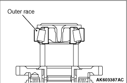
1.Set the output shaft assembly to the clutch housing assembly.
|
|
2.Push and fit the tapered roller bearing outer race by hand.
3.To fit the tapered roller bearing outer race, rotate the output shaft assembly by
hand.
|
|
4.Put the clutch housing assembly on the surface table and measure the dimension "A" which
is from the mating surface of the clutch housing assembly to the end surface of the bearing
outer race, with a height gauge.
|
|
5.Put the straight edge on the mating surface of the transmission case assembly and measure
the dimension "B" with a vernier caliper.
6.Select the shim whose dimension is the difference between "B" and "A."
7.Install the output shaft assembly and differential assembly to the clutch housing
assembly. Tighten the transmission case bolts to the specified torque of 29 ± 5.8 N·m.
8.Place the selected shim, then install the output shaft assembly.
9.Install the rear bearing retainer mounting bolt to specified torque of 42 ± 8
N·m.
|
|
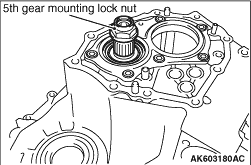
10.Install the 5th gear mounting lock nut to measure rotational starting torque.
|
|
11.Measure the rotational starting torque of output shaft. When it is not within the standard
range, reselect the shim.
Standard value: 0.8 - 1.6 N·m
|

|
1.Install the reverse idler gear sub-assembly, reverse idler thrust washer and reverse idler
gear shaft.
2.Before installing the transmission case assembly, confirm that the reverse idler gear
addition mark is positioned as show in the illustration.
|
|
|
1.Fit the shaft snap ring onto the gear shaft fork shaft No.1.
|
|
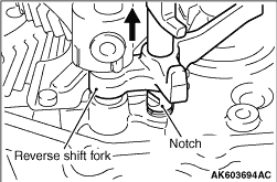
2.Bring up the notch in the gear shift fork shaft No.3 to the reverse shift fork into neutral
position, and move the roller in the reverse shift fork to the gear shift fork shaft No.3 side.
|
|
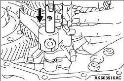
3.Pass the gear shift fork shaft No.1 through the gear shift fork No.1 and reverse shift
fork in that order, then install it to the clutch housing assembly.
|
|
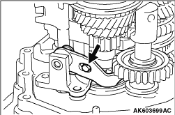
Fit the arm tip of the reverse shift fork into the mating slot in the reverse shift arm
bracket assembly.
|
|
1.Completely degrease the FIPG-applied surface so that water and oil including the old sealant
cannot adhere to the surface coated with the sealant.
Never touch the degreased surface by hand.
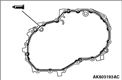
2.Apply a 1.2 mm diameter bead of sealant as illustrated onto the transmission case
sub-assembly.
Specified sealant: MITSUBISHI MOTORS GENUINE Part No. MD997740 or equivalent
|
|
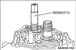
1.Install special tool Output shaft adapter (MB992219) until it hits the end face of the
output shaft.
|
|
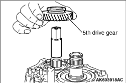
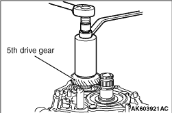
2.Install the 5th drive gear.
|
|
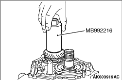
3.Set special tool Installer (MB992216) on top of the 5th drive gear.
|
|
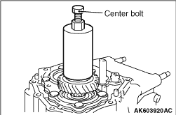
4.Install the centre bolt that is included in the set of special tool Installer (MB992216)
as shown.
|
|
5.Press-fit the 5th drive gear as shown.
|
|
1.Using special tool Input shaft holder (MD998802), lock the input shaft.
|
|
2.Install the flange nut from output shaft assembly.
3.Tighten the flange nut to the specified torque of 123 ± 36 N·m.
4.Stake the flange nut.
|
|
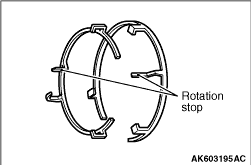
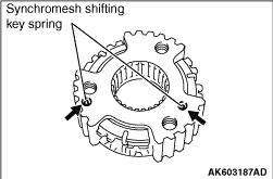
1.Install the synchromesh shifting key springs No.3 onto the synchronizer ring assembly
holding the claws and rotation stops of the key springs in the illustrated positions.
|
|
2.Make sure that the rotation stops of the synchromesh shifting key springs No.3 fit into
the mating holes in the synchronizer ring set No.5.
|
|
3.Compress the key springs into place inside the hub as shown.
|
|
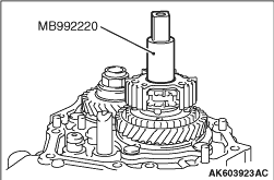
4.Install special tool Input shaft adapter (MB992220) until it hits the end face of the
input shaft.
|
|
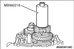
5.Set special tool Installer (MB992216) on top of the synchronizer clutch hub No.3.
|
|
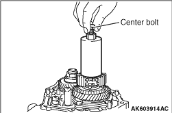
6.Install the centre bolt that is a part of the set of special tool Installer (MB992216)
as shown.
|
|
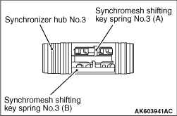
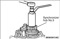
7.Press-fit the synchronizer clutch hub No.3 as shown.
|
|
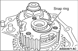
Select a shaft snap ring that allows distance of the thrust crevice of synchronizer hub
No.3 to fall within the standard value range.
Standard value: 0 - 0.1 mm
| note |
Try on snap rings in the decreasing order of thickness, and install the first one that
fits into the hub.
|
|
|
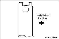
Put the synchronizer hub sleeve No.3 and gear shaft fork assembly No.3 together, then
install the synchronizer hub sleeve No.3 in the illustrated direction.
|
|
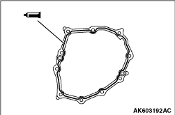
1.Completely degrease the FIPG-applied surface so that water and oil including the old sealant
cannot adhere to the surface coated with the sealant.
Never touch the degreased surface by hand.
2.Apply a 1.2 mm diameter bead of sealant as illustrated onto the transmission case
cover sub-assembly.
Specified sealant: MITSUBISHI MOTORS GENUINE Part No. MD997740 or equivalent
|
|
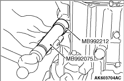
1.Using special tools to install the oil seal.
- Oil seal installer (MB992212)
2.Pack grease to the oil seal lip area
Specified grease: MITSUBISHI MOTORS GENUINE Part No. 0101011 or equivalent
|
|
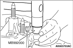
Using special tool Crankshaft adapter (MB992000), install the air breather.
|
|
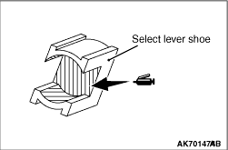
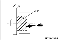
1.Apply grease to the select lever shoe hole and bellcrank pin.
Specified grease: MITSUBISHI MOTORS GENUINE Part No. 0101011 or equivalent
2.Install the select lever shoe to the bellcrank.
|
)

)
)
)
)
)
)
)
)
)
)
)
)
)
)
)
)
)
)
)
)
)
)
)
)
)
)
)
)
)
)
)
)
)
)
)
)
)
)
)
)