|
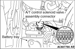
1.Disconnect the A/T control solenoid valve assembly connector.
2.Measure the resistance between the terminals of the applicable solenoid valves and terminal No.13.
Standard value:
|
|
Terminal No.
|
Applicable solenoid valve
|
Resistance value Ω
|
1
|
Low clutch linear solenoid valve
|
Approximately 5.3 {A/T fluid temperature: 20°C}
|
4
|
Lock-up and low reverse brake linear solenoid valve
|
6
|
2-6 brake linear solenoid valve
|
9
|
Line pressure linear solenoid valve
|
14
|
3-5 reverse clutch linear solenoid valve
|
19
|
High clutch linear solenoid valve
|
17
|
Low-reverse brake shift solenoid valve
|
Approximately 28 {A/T fluid temperature: 20°C}
|
22
|
Low clutch shift solenoid valve
|
|
3.When the resistance is within the standard value, check the power supply and the earth circuits.
4.
| caution |
Each solenoid valve cannot be removed or replaced as a single unit. When replacement of any one of the solenoid valves is necessary, replace the valve body assembly.
|
When the resistance is outside the standard value, replace the valve body assembly and the harness.
|
)