|
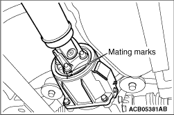
Put mating marks on the flange yoke and the electronic control coupling, then remove the
connecting nuts.
|
|
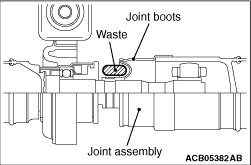
1.
| caution |
If the joint assembly is bent, it may be damaged when pinching
the joint boots.
|
Insert a waste or similar materials into the joint boots, and remove the propeller shaft
assembly by aligning the front propeller shaft with the rear shaft.
|
|
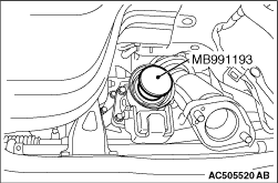
2.Using special tool plug (MB991193), cover the transfer case to prevent the entry of foreign
materials.
|
|
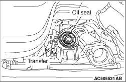
| caution |
- Do not damage the oil seal lip of the transfer.
- The mounting bolt and nut may be loosened if oil or grease is stuck on the threads
of the bolt and nut. Tighten them after degreasing the threads.
- If the joint assembly is bent, it may be damaged when pinching the joint boots.
|
|
|
|
If the propeller shaft is reused, align the mating marks and install the connecting nuts.
|
|
|
Tightening torque: 54 ± 5 N·m
|
 .)
.))
)
)
)
)