|
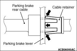
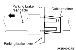
Compress the tabs on the cable retainer to pull out the parking rear cable through the
parking lever hole of the rear brake caliper assembly.
|
|
| note |
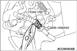
- When pulling out the parking rear cable, be careful not to damage the tab on the
cable retainer.
- Example: Insert the 12.8-mm hose clip (MB248923) into the parking rear cable. Then push
the clip over the cable retainer to protect the tabs.
|
|
|
1.
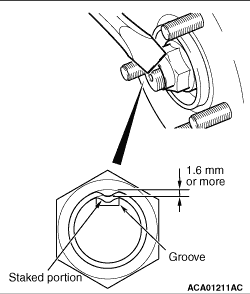
| caution |
- Make sure that the lock
nut chisel is set in the correct direction. Otherwise, the groove or thread in the driveshaft
may be broken, or the tip of the chisel may be chipped.
- Never use a chisel which tip is damaged.
- For how to use the lock nut chisel, refer to the manufacturer’s operating
instructions.
|
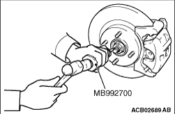
Set the special tool lock nut chisel (MB992700) in the groove of the driveshaft with its
"UPPER" mark facing upwards. Then strike the staked portion of the driveshaft nut with the chisel
and a hammer to raise up.
|
|
2.
| caution |
Be careful not to damage the thread of the driveshaft.
|
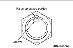
Raise up the staked portion of the driveshaft nut until it does not interfere with the
shaft thread.
|
|
3.
| caution |
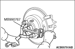
- Never use a impact wrench to loosen the
driveshaft nut.
- Do not apply the vehicle weight on the wheel bearing with the driveshaft nut loosened.
Otherwise, the wheel bearing may be broken.
|
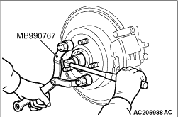
Use special tool front hub and flange yoke holder (MB990767) to counter the hub, and remove
the driveshaft nut.
|
|
|
1.Remove the caliper assembly with brake hose.
|
|
|
2.Secure the removed caliper assembly with a wire or other similar material at a position
where it will not interfere with the removal and installation of the rear wheel hub assembly.
|
|
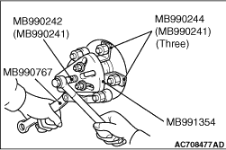
1.If the rear wheel hub assembly is seized with the rear driveshaft assembly, use the following
special tools to push the rear driveshaft assembly out from the hub and then remove the rear
wheel hub assembly.
- Puller shaft (MB990242)
- Puller bar (MB990244)
- Puller body (MB991354)
- Front hub and flange yoke holder (MB990767)
|
|
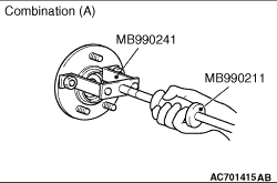
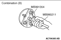
2.If the rear wheel hub assembly is seized with the knuckle, use the following special tools
to remove the rear wheel hub assembly.
Combination (A)
- Slide hammer (MB990211)
- Rear axle shaft puller (MB990241)
Combination (B)
- Slide hammer (MB990211)
- Puller body (MB991354)
|
|
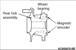
| caution |
- The wheel speed detection magnetic encoder collects metallic particles easily,
because it is magnetized. Make sure that the magnetic encoder should not collect metallic particles.
Check that there is not any trouble prior to reassembling it.
- When installing the drive shaft, make sure that it does not contact with the wheel
speed detection magnetic encoder (integrated with the inner oil seal) to avoid damage.
- Do not apply the vehicle weight on the rear wheel hub assembly before fully tightening
the driveshaft nuts. Otherwise, the wheel bearing will be broken.
|
1.Check the hub seated surface for damage or corrosion. Whenever solvent is used for
removing the corrosion, the surface should be degreased.
2.Check that the new driveshaft nut can be turned smoothly by hand. Then tighten it
until it is seated.
|
|
3.4.Using special tool front hub and flange yoke holder (MB990767), tighten the driveshaft
nut.
Tightening torque: 270 ± 27 N·m
5.After tightening to the specified torque, check that the nut is seated securely.
|
|
6.Use the chisel and a hammer to stake the nut until the centre in the staked portion reaches
the shown dimension.
7.Finally, check that the nut is not cracked at its staked portion.
|
|
|
1.Guide the parking brake rear cable through the parking lever hole of the rear brake
caliper assembly to the cable retainer.
|
|
2.Pull back the parking brake rear cable to assure it is tightly fastened to the cable retainer.
|
)

)
)
)
)
)
)
)
)
)
)
)
)