|
1.
| caution |
The locking nut for the piston rod inside the shock absorber
may be loose. Do not use an impact wrench to loosen the self-locking nut.
|
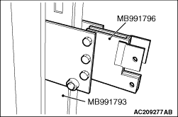
Install special tool spring compressor (MB991796) to special tool attachment B (MB991793)
as shown in the figure.
|
|
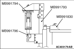
2.Set the shock absorber assembly to the following special tools:
- Spring compressor (MB991793)
- Attachment B (MB991796)
- Upper plate (MB991794)
- Fixture (MB991830)
| note |
Use the bolts and nuts removed from the vehicle to secure the shock absorber assembly
and tighten them lightly by hand.
|
3.After setting the shock absorber assembly, operate the spring compressor and compress
the coil spring by approximately 5 mm.
|
|
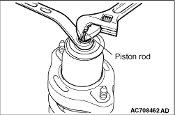
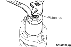
4.While holding the piston rod as shown in the figure, remove the self-locking nut.
|
|
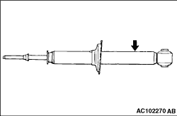
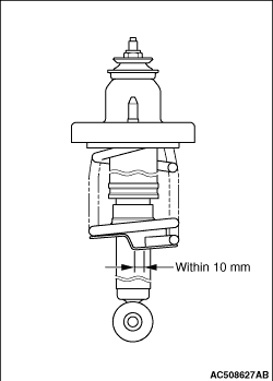
Before disposal of the shock absorber, place the shock absorber on the level surface with
the piston rod extended, and make a hole of approximately 3 mm in diameter at the point shown
in the figure to discharge the gas.
|
|
1.Align the end of the coil spring with the shock absorber as shown in the figure.
|
|
2.Set the shock absorber assembly to the following special tools:
- Spring compressor (MB991793)
- Attachment B (MB991796)
- Upper plate (MB991794)
- Fixture (MB991830)
| note |
Use the bolts and nuts removed from the vehicle to secure the shock absorber assembly
and tighten them lightly by hand.
|
|
|
Counter the piston rod of the shock absorber as shown in the figure, and tighten the self-locking
nut to the specified torque.
Tightening torque: 25 ± 5 N·m
|
)

)
)
)
)
)
)