|
|
1.Raise the vehicle using a jack and support the specified points with a rigid rack.
|
|
|
2.
| caution |
Before connecting or disconnecting M.U.T.-III, always
turn the ignition switch to the LOCK (OFF) position.
|
Before setting M.U.T.-III, turn the ignition key to the LOCK (OFF) position.
|
|
|
3.Confirm that the selector lever is in the "N" position, and then start the engine.
|
|
|
4.When carrying out the actuator tests No. 01 to 04, perform the actuator tests using
M.U.T.-III while depressing the brake pedal. When carrying out the actuator tests, rotate the wheel
by hands to confirm that the braking force changes.
| note |
- While performing the actuator test, the ABS warning lamp flashes at a rate of 2
Hz.
- When ABS-ECU is disabled due to the fail-safe function, the M.U.T.-III actuator
test cannot be performed.
- After the actuator test has been performed, the ABS warning lamp and brake waning
lamp illuminate until the ignition switch is turned to ON again or the communication between
M.U.T.-III and ABS-ECU is terminated.
|
|
|
|
5.
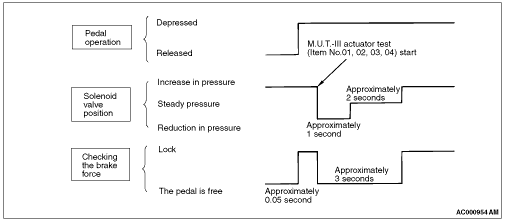
This is indicated as shown in the above.
|
|
|
6.When any malfunction has been found, take a necessary action according to the "Judgement
Table."
|
|
|
7.After the inspection, turn the ignition switch to the LOCK (OFF) position, and then
disconnect M.U.T.-III.
|
|
|
1.Operate the pre-removal steps for the hydraulic unit. (Refer to  .) .)
|
|
|
2.Remove all brake tubes.
|
|
|
3.Loosen the mounting bolt and nut of the hydraulic unit bracket.
|
|
|
4.Install all brake tubes temporarily.
|
|
|
5.Shake hydraulic unit to all directions with both hands to make the hydraulic unit
bracket insulator fit with the unit.
|
|
|
6.Install the hydraulic unit bracket with mounting bolt and nut not to load the brake
tube.
|
|
|
7.Install all brake tubes securely.
| note |
Install the flare nut taking care not to let the brake tube turn together.
|
|
|
|
8.Operate the post-installation steps of the hydraulic unit. (Refer to .)
|
)