|
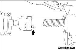
Roll back the right bellows and turn the steering wheel anticlockwise to the stop. Then
counterhold the rack at the flattened surfaces as shown to remove the tie rod.
|
|
Turn the steering wheel anticlockwise to the stop. Then counterhold the rack at the flattened
surfaces as shown to remove the tie rod.
|
|
1.
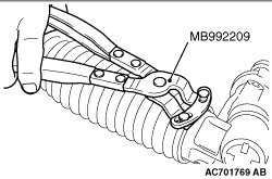
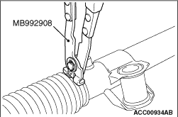
| caution |
- Hold the rack housing, and use special tool bellows band
crimping tool (MB992209 or MB992908) to crimp the bellows band securely.
- Crimp the bellows band until special tool (MB992209 or MB992908) touches the stopper.
|
Use special tool (MB992209 or MB992908) to crimp the bellows band.
|
|
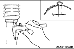
2.Check that crimped width (A) is within the standard value.
Standard value (A): 2.4 - 2.8 mm
|
|
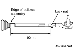
Screw in the tie-rod to the length shown in the figure, and hand-tighten the lock nut.
| note |
Install the steering gear & linkage to the body, adjust the toe-in, and then
tighten the lock nut to the specified torque.
|
|
)

)
)
)
)
)
)