|
|
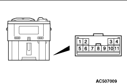
Remove the door trim, and then connect the battery to the door mirror assembly connector
to check that the door mirror operates.
|
|
|
|
Battery connection
|
Operation direction
|
- Connect terminal 12 to the negative battery terminal.
- Connect terminal 5 to the positive battery terminal.
|
Up
|
- Connect terminal 12 to the positive battery terminal.
- Connect terminal 5 to the negative battery terminal.
|
Down
|
- Connect terminal 13 to the negative battery terminal.
- Connect terminal 12 to the positive battery terminal.
|
Right
|
- Connect terminal 13 to the positive battery terminal.
- Connect terminal 12 to the negative battery terminal.
|
Left
|
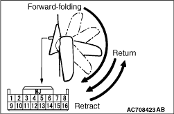
- Connect terminal 11 to the positive battery terminal.
- Connect terminal 4 to the negative battery terminal.
|
Retract
|
- Connect terminal 11 to the negative battery terminal.
- Connect terminal 4 to the positive battery terminal.
|
Return
|
|
|
|
|
|
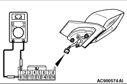
Switch position
|
Tester connection
|
Specified condition
|
Left side
|
Up
|
1 - 6, 9 - 11
|
Continuity
exists(2 Ω or less)
|
Down
|
1 - 11, 6 - 9
|
Right
|
1 - 6, 9 - 10
|
Left
|
1 - 10, 6 - 9
|
Right side
|
Up
|
1 - 6, 3 - 9
|
Down
|
1 - 3, 6 - 9
|
Right
|
1 - 6, 2 - 9
|
Left
|
1 - 2, 6 - 9
|
Retract and return
|
1 - 4
|
|
|
|
Check that the resistance value between the connector terminals is at the standard value.
Standard value: 7.2 ± 1.4 Ω at 25°C
|
)
)
)