|
|
Follow the procedure below according to the item numbers in the illustration.
|
|
|
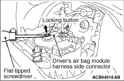
1.Insert a flat-tipped screwdriver into the service hole on the steering wheel assembly.
|
|
|
2.Use the flat-tipped screwdriver to press the rod in driver’s air bag module.
|
|
|
3.When the driver’s air bag module is disengaged, the driver’s air
bag module will be released.
|
|
|
4.Repeat for the other service hole end then remove the driver’s air bag module.
|
|
1.Use the flat-tipped screwdriver to pull out the locking button of wiring harness side
connector, and release the lock.
|
|
|
1.
| caution |
Use the special tool to remove the steering wheel since
the steering column collision absorbing mechanism may be damaged.
|
Position the steering wheel in a straight ahead direction.
|
|
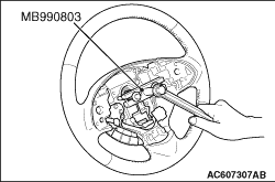
2.Using special tool steering wheel puller (MB990803), remove the steering wheel assembly
as shown in the figure.
|
|
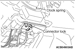
Lift the connector lock of clock spring connector to the direction of the arrow, then
unlock and disconnect the connector.
|
|
|
1.Before the installation, check the air bag module and clock spring (Refer to  ). ).
| note |
Even when installing a new air bag module or clock spring, perform an inspection before
the installation.
|
|
|
|
2.Connect the negative (-) battery terminal.
|
|
|
3.
| caution |
Be sure to turn the ignition key to the LOCK (OFF) position when
connecting or disconnecting M.U.T.-III.
|
Connect M.U.T.-III to the diagnosis connector (16 pin).
|
|
|
4.Turn the ignition switch to the ON position.
|
|
|
5.Read the diagnosis code, and check that everything is normal except the air bag module
open circuit.
|
|
|
6.Turn the ignition switch to the LOCK (OFF) position.
|
|
1.
| caution |
- If the centre of the
clock spring is not correctly aligned, the steering wheel may not be turned fully or the cable inside
the clock spring may be broken, causing the SRS airbag to be inoperative or operated incorrectly.
- When aligning the clock spring neutral position mark, perform with
the clock spring independently. If performed with the steering wheel sensor installed, the steering
wheel sensor may be damaged.
|
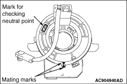
Align the mating marks of the clock spring.
<Alignment of mating marks>
(1)
Turn the clock spring clockwise fully.
(2)
Turn the clock spring anti-clockwise approximately two and 9/10 turns to
align the mating marks.
(3)
Check that the orange roller can be seen from the window for checking the neutral
point when the mating marks are aligned.
|
|
| note |
If the orange roller cannot be seen or black roller can be seen, the neutral point is
not aligned correctly.
|
|
(4)
Install the clock spring to the column switch.
|
|
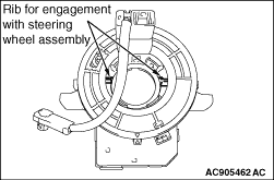
1.
| caution |
When installing the steering wheel assembly, do not trap the
clock spring harness.
|
After checking that the clock spring centre alignment is already performed, install the
steering wheel assembly so that its boss part is aligned with the rib of the clock spring slowly.
2.After the installation, check that there is no abnormality when the steering wheel
is fully turned to left and right.
|
|
|
1.Connect the negative (-) battery cable.
|
|
|
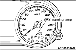
2.Turn the ignition switch to the "ON" position.
|
|
3.Check that the SRS warning lamp is illuminated for 6 to 8 seconds, and extinguished afterward.
4.If the lamp does not extinguish, perform the troubleshooting (Refer to ).
|
)
)
)
)
)
)
)
)