|
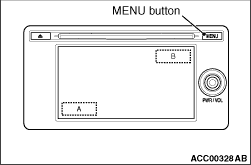
1.While pressing the "MENU" button, press "A" portion (shown in the illustration)
on the display briefly. Then press "B" portion for at least two seconds.
|
|
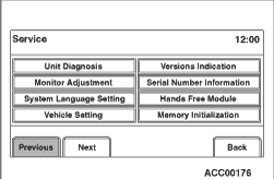
2.The service mode will be initiated. Then "Service" screen will be displayed.
|
|
|
If the operations below are done, the service mode will be terminated.
|
|
|
- If "Back" button is selected on "Service" screen, the service mode
will terminate and then return to the previous screen.
|
|
|
The following items can be checked or set in the service mode.
|
|
|
- Unit Diagnosis
- Monitor Adjustment
- System Language Setting
- Versions Indication
- Serial Number Information
- Hands Free Module
- Memory Initialization
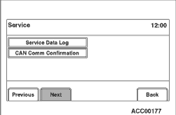
- Service Data Log
- CAN Comm Confirmation
|
|
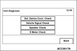
1.Select "Ext. Device Conn. Check" button on "Unit Diagnosis" screen.
|
|
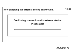
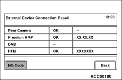
2."Now checking the external device connection." will appear, and then
it will switch to "External Device Connection Result" screen.
- If the connection with an equipment is detected, "OK" will be displayed.
- If the connection with an equipment is not detected, "--" will be displayed.
- In case other than above, "NG" is displayed.
|
|
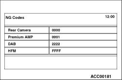
3.If "NG" is displayed on the check result screen, "NG code" will be displayed
by pressing the respective button on "External Device Connection Result" screen.
| note |
If "NG" is not displayed at all, "NG code" button is not active.
|
|
|
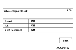
1.Select "Vehicle Signal Check" on "Unit Diagnosis" screen.
|
|
2.The current status of vehicle signal will be displayed.
- "Speed": "ON" when the vehicle speed is 6 km/h
or more, and "OFF" when the vehicle speed is 4 km/h or less.
- "ILL": "ON" when the lighting switch is on (the tail lamps or the
headlamps are ON), and "OFF" when the tail lamps or the headlamps are OFF.
- "Shift Position R": "ON" when the selector lever is at R position,
and "OFF" when it is at the other position.
|
|
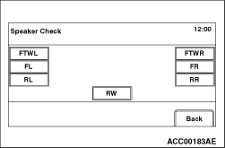
1.Select "Speaker Check" button on "Unit Diagnosis" screen.
|
|
2.Select a speaker to be checked, and play test tone through the speaker.
|
|
Screen display
|
The speaker which sounds a test tone
|
FL
|
Front door speaker (LH), front tweeter (LH)
|
FR
|
Front door speaker (RH), front tweeter (RH)
|
RL
|
Rear door speaker (LH)
|
RR
|
Rear door speaker (RH)
|
FTWL
|
No test tone issued
|
RTWR
|
RW
|
|
| note |
- By operating the volume key, the volume can be changed.
- During the test, only the selected speaker sounds. If "Back" is selected during
the test, the test tone will disappear.
|
|
|
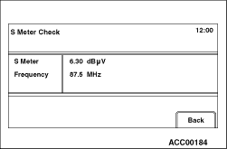
1.Select "S Meter Check" button on "Unit Diagnosis" screen.
|
|
2.Field intensity and frequency of the station currently tuned is displayed.
|
|
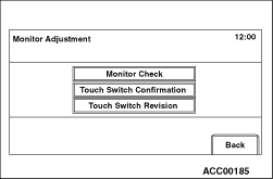
1.Select "Monitor Check" button on "Monitor Adjustment" screen.
|
|
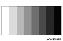
2.Eight colour bars are displayed.
|
|
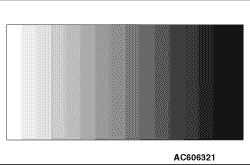
3.By touching the colour bar screen, it will be switched to 16-gradient
greyscale pattern.
|
|
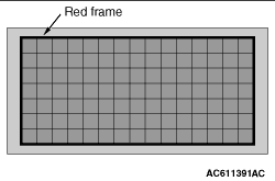
4.By touching the greyscale screen, it will be switched to a cross-hatch
pattern. (Check whether the full-scale red frame is not misaligned)
|
|
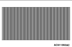
5.By touching the cross-hatch screen, it will be switched to a monocolour
vertical stripe screen.
|
|
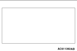
6.By touching the vertical stripe screen, it will be switched to a full-scale
white screen.
|

|
7.By touching the full-scale white screen, it will be switched to a full-scale
black screen.
|

|
8.By touching the full-scale black screen, it will be switched to a full-scale
red screen.
|
|
9.By touching the full-scale red screen, it will be switched to a full-scale
green screen.
|

|
10.By touching the full-scale green screen, it will be switched to a full-scale
blue screen.
11.By touching the full-scale blue screen, it will be switched back
to "Monitor Adjustment" screen.
|
|
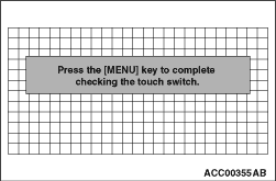
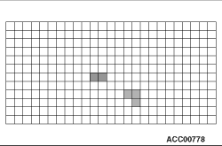
1.Select "Touch Switch Confirmation" button on "Monitor Adjustment" screen.
|
|
2.If you touch the screen, the colour of the dotted coordinate at the touched
area will be changed.
|
|
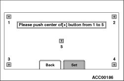
1.Select "Touch Switch Revision" button on "Monitor Adjustment" screen.
|
|
2.Select "Set" button according to the instructions on the screen.
3.When the confirmation button is selected after the adjustment, it
will be switched back to "Monitor Adjustment" screen.
|
|
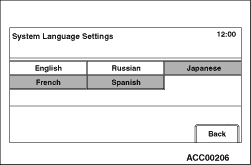
1.Select "System Language Setting" button on "Service" screen.
|
|
2.Select your desired language. After a language is selected, it will be
switched back to "Service" screen.
| note |
After a "Back" button is selected, it will be also switched back to "Service"
screen.
|
|
|
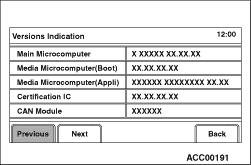
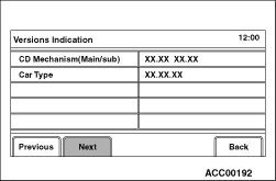
1.Select "Versions Indication" button on "Service" screen.
|
|
2.A version information will be displayed.
|
|
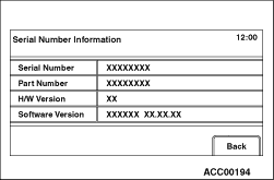
1.Select "Serial Number Information" button on "Service" screen.
|
|
2.A hardware identification number will be displayed.
|
|
|
Refer or Hands Free-ECU - Service Mode  . .
|
|
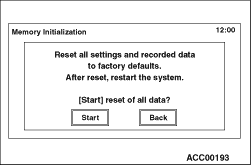
1.Select "Memory Initialization" button on "Service" screen.
|
|
2."Memory Initialization" screen will be displayed. When you select "Start"
button, the initialisation process will be executed.
| note |
After a "Back" button is selected, it will be switched back to "Service"
screen.
|
3.After the memory initialisation is successfully completed, the system will restart
automatically.
|
|
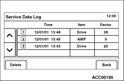
1.Select "Service Data Log" button on "Service" screen.
|
|
2.The error log, which is stored during a system failure (drive failure),
will be displayed.
| note |
- Up to ten error logs can be stored.
- The error logs in the list are sorted in descending order from
new to old.
- When you select "Delete" button, all of the stored error logs will
be erased.
|
|
|
EACH LOG INFORMATION: FACTOR CODE TABLE
Item
|
Factor number
|
Produced log
|
Drive
|
20
|
Log concerning focus
|
21
|
Log concerning disc type
|
22
|
Log concerning disc
|
25
|
Log concerning SEEK
|
26
|
Log concerning servo start-up
|
27
|
Log concerning power-On
|
28
|
Log concerning loading / eject operation
|
29
|
Log concerning pick-up operation
|
30
|
Log concerning state of mechanism
|
52
|
Log concerning TOC reading
|
HDD
|
1
|
Log concerning high temperature
|
2
|
Log concerning low temperature
|
Monitor
|
1
|
Log concerning high temperature
|
AMP
|
0
|
Log concerning connection
|
15
|
Log concerning communication
|
SP*1
|
1,2,8,15
|
Log concerning number of speakers unexpected
|
CAR*2
|
0 -12, 130, 131, 160, 192, 255
|
Log concerning vehicle model unexpected
|
|
| note |
*1: The log is displayed when the number of speakers is unexpected.
*2: The log is displayed when the vehicle model is unexpected.
|
|
|
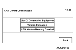
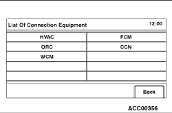
1.Select "List Of Connection Equipment" button on "CAN Comm Confirmation"
screen.
|
|
2.The system will search device(s), which are connected via CAN, and display
the list of the devices.
|
|
List of connected devices
Screen indication
|
Equipment
|
HVAC
|
A/C-ECU
|
FCM
|
ETACS-ECU
|
ORC
|
SRS-ECU
|
CCN
|
Combination meter
|
WCM
|
Wireless control module
|
|
|
|
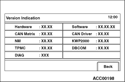
1.Select "Versions Indication" button on "CAN Comm Confirmation" screen.
|
|
2.A CAN version information will be displayed.
|
|
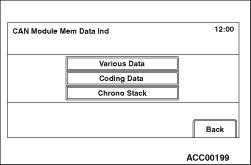
1.Select "CAN Module Memory Data Ind" button on "CAN Comm Confirmation"
screen.
|
|
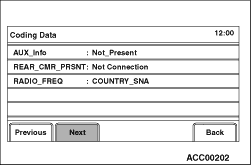
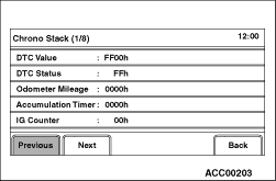
2."CAN Module Memory Data Ind" will be displayed. A respective data will
be displayed by selecting each button ("Various Data", "Coding data", "Chrono Stack").
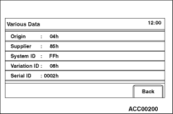
- Select "Various Data."
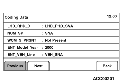
- Select "Coding Data."
- Select "Chrono Stack."
|
)
)
)
)
)
)
)
)
)
)
)
)
)
)
)
)
)
)
)
)
)
)
)
)
)
)
)
)
)
)
)
)
)
)
)
)
)