Tool
|
Number
|
Name
|
Use
|
|
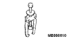
MB990810
|
Side bearing puller
|
A/C compressor rotor removal and installation
|

|
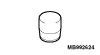
MB992623
|
Guide
|
|
MB992624
|
Pusher
|
|
MD999566
|
Claw
|
|
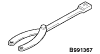
MB991367
|
Special spanner
|
Removal and installation of the A/C compressor armature
mounting nut
|
|
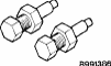
MB991386
|
Pin
|
|
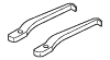
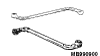
MB990900 or MB991164
|
Door hinge adjusting wrench
|
Removal and installation of front deck cross member heater unit assembly
|
|
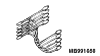
MB991658
|
Test harness
|
Inspection of the A/C pressure sensor
|
|
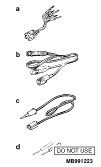
MB991223
- MB991219
- MB991220
- MB991221
- MB991222
|
Harness set
- Test harness
- LED harness
- LED harness adapter
- Probe
|
Making voltage and resistance measurements during troubleshooting
- Connect pin contact pressure inspection
- Power circuit inspection
- Power circuit inspection
- Commercial tester connection
|
|
MB992006
|
Extra fine probe
|
Continuity check and voltage measurement at harness wire or connector
|
|
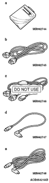
- MB992744
- MB992745
- MB992746
- MB992747
- MB992748
|
- Vehicle communication interface-Lite
(V.C.I.-Lite)
- V.C.I.-Lite main harness A (for vehicles with CAN communication)
- V.C.I.-Lite main harness B (for vehicles without CAN communication)
- V.C.I.-Lite USB cable short
- V.C.I.-Lite USB cable long
|
Check the A/C (The M.U.T.-III diagnosis codes display, service data
display and actuator test)
|
|
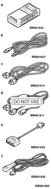
MB991955
- MB991824
- MB991827
- MB991910
- MB991911
- MB991825
- MB991826
|
M.U.T.-III sub-assembly
- Vehicle Communication Interface (V. C. I).
- USB cable
- M.U.T.-III main harness A (applicable to vehicles with CAN communication)
- M.U.T.-III main harness B (applicable to vehicles without CAN communication)
- Measurement adapter
- Trigger harness
|
| caution |
For vehicles with CAN communication,
use M.U.T.-III main harness A to send simulated vehicle speed. If you connect M.U.T.-III main harness
B instead, the CAN communication does not function correctly.
|
Check the A/C (The M.U.T.-III diagnosis codes display, service data display and actuator
test)
|
)
)
)
)
)
)
)
)
)
)
)
)