|
|
Check that the temperature/humidity of measurement location satisfies the test
conditions, and then set the vehicle body conditions to the designated status according to the
test conditions. If the temperature/humidity is not within the test conditions, an
accurate judgment cannot be made. Therefore, postpone the performance test.
|
|
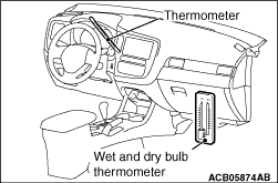
1.Insert a thermometer into the air outlet located at the centre of instrument panel.
| note |
Set a thermometer so that cool air from the air outlet blows directly against the sensing
part.
|
2.Set a wet and dry bulb thermometer in the air intake of the front passenger’s
foot area (below the glove box).
| note |
Set a wet and dry bulb thermometer so that cool air does not blow against it.
|
3.Start the engine to warm up. Confirm that the engine speed of the test condition is
satisfied.
4.Set the A/C control panel to the mode instructed in the test conditions.
5.Wait until the air outlet temperature is stable (approximately 10 minutes after the
A/C starts), and measure dry-bulb/wet-bulb temperatures at the air outlet
and the air intake.
6.If the air outlet temperature is in the range specified by the table below, it is
judged normal. If the temperature is outside the permissible range in the table below, refer
to the refrigerant gas pressure inspection result, and check each section according to the diagnosis
chart of refrigerant system.
|
|
1.
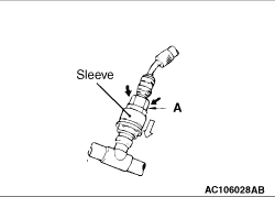
| caution |
- Place the quick joint onto the service valve, and press to fit the part A securely until
the sleeve clicks into place.
- When connecting, run your hand along the hose while pressing to ensure that there
are no bends in the hose.
|
Check that the engine and A/C are stopped.
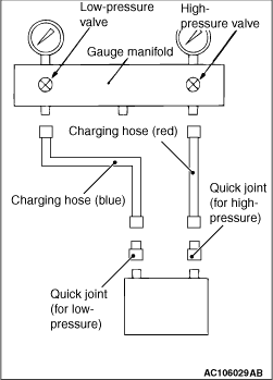
2.Close the high-pressure valve of the gauge manifold.
3.Connect the charging hose (red) to the hi-pressure side of the gauge manifold.
4.Connect the quick joint (for high pressure) to the charging hose (red).
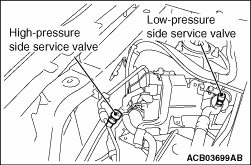
5.Install the quick joint (for high pressure) to the high-pressure side service valve
of the vehicle.
6.Close the low-pressure valve of the gauge manifold.
7.Connect the charging hose (blue) to the low-pressure side of the gauge manifold.
8.Connect the quick joint (for low pressure) to the charging hose (blue).
9.Install the quick joint (for low pressure) to the low-pressure side service valve
of the vehicle.
10.Start and fully warm up the engine, and then check that the engine speed of the test
condition is satisfied.
11.Set the A/C control panel to the mode instructed in the test conditions.
12.Measure the high pressure/low pressure, and check that the measurement is
within the permissible range of the table below. If the value is outside the permissible range,
refer to the cooling performance check result, and perform a check according to the diagnosis
chart of refrigerant system.
| note |
Prior to the measurement, wait until the refrigerant pressure is stable. (Approximately
10 minutes after A/C operation start)
|
|
)
)
)
)