|
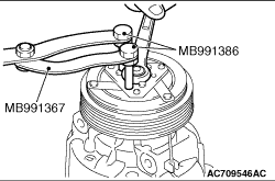
Use the special tools below to remove the self-locking nut.
|
|
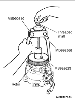
| caution |
- Be sure to use the guide (MB992623) when the side bearing puller
(MB990810) is used to prevent the damage of A/C compressor.
- If the threaded shaft of side bearing puller (MB990810) is turned than necessary,
the rotor may be distorted. Therefore, turn the threaded shaft lightly only by hand without
using any tools.
|
Rotor can be removed by hand, but if it is difficult to remove it, use the guide (MB992623)
and the side bearing puller (MB990810) as shown.
|
|
|
Check that O-ring is installed to the high-pressure relief and use the adjust torque wrench
to install the high-pressure relief valve to the main body of the compressor.
|
|
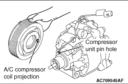
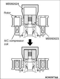
Line up the pin hole on the compressor unit with the A/C compressor coil projection
and attach.
|
|
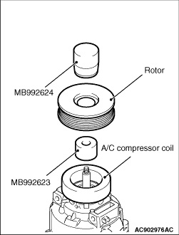
Install the rotor while pushing the inner wheel side slowly using the pusher (MB992624)
and guide (MB992623).
| note |
Insert the rotor in a direction perpendicular to the A/C compressor.
|
|
|
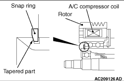
Using snap ring pliers, fit the snap ring so that the snap ring’s tapered part
is on the outside.
|
|
Using a special tool, as when removing the nut, secure the armature and tighten the self-locking
nut.
|
|
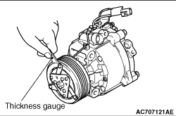
Check whether or not the air gap of the clutch is within the standard value.
Standard value:
| note |
If there is a deviation of the air gap from the standard value, make the necessary adjustment
by adjusting the number of shims.
|
|
)

)
)
)
)
)
)
)