|
|
1.Pull off front sealing flange.
|
|
|
2.Remove sealing flange; if necessary, loosen by applying light blows with a rubber-headed
hammer.
|
|
|
3.Remove sealant residue on cylinder block with a flat scraper.
|
|
4.Remove residual sealant from sealing flange using a plastic rotary brush (wear eye protection).
5.Clean sealing surfaces. They must be free of oil and grease.
|
|
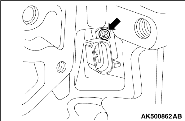
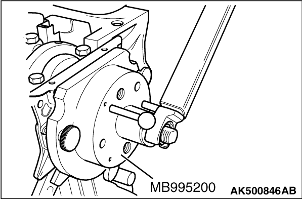
Remove securing bolt as shown in the illustration, and pull out crank angle sensor.
|
|
|
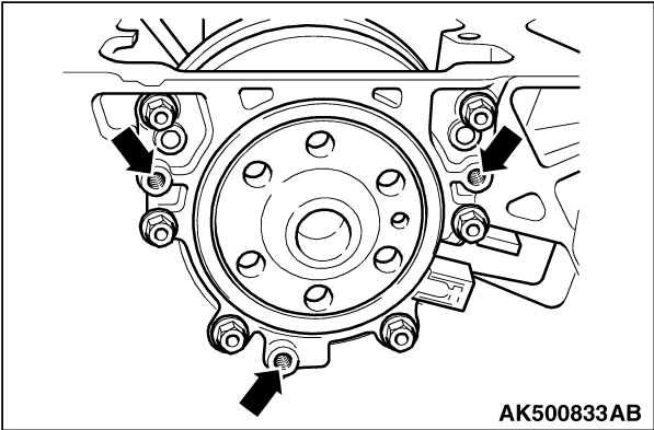
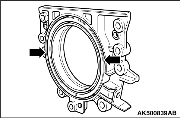
1.Undo sealing flange securing bolts.
| note |
Sealing flange and sender wheel are pressed off the crankshaft together using three M6 × 35
mm bolts.
|
|
|
2.Screw three M6 × 35 mm bolts into threaded holes 35 mm of sealing flange as shown
in the illustration.
3.Screw bolts alternately (maximum 1/2 turn (180°) for each bolt) into sealing
flange and press sealing flange together with sender wheel off crankshaft.
|
|
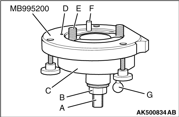
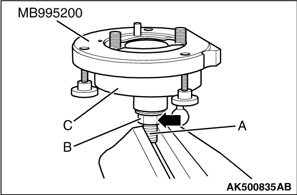
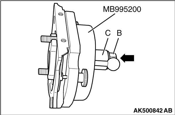
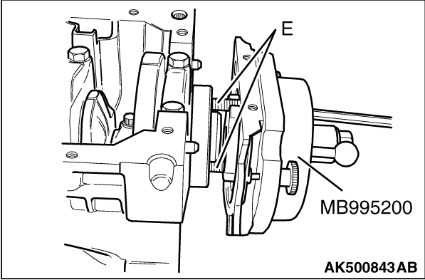
special tool Oil seal installer (MB995200)
- A: Clamping surface
- B: Hexagon nut
- C: Assembly bell housing
- D: Locating pin
- E: Hexagon socket head bolt
- F: Guide pin for diesel engines (red knob)
- G: Guide pin for petrol engines (black knob)
1.Screw in hexagon nut to just before clamping surface of threaded spindle.
|
|
2.Clamp special tool Oil seal installer (MB995200) in a vice on clamping surface "A" of
threaded spindle.
3.Press assembly bell housing "C" downwards so that it lies on hexagon nut "B" as shown
in the illustration.
4.Screw hexagon nut "B" onto threaded spindle completely down.
|
|
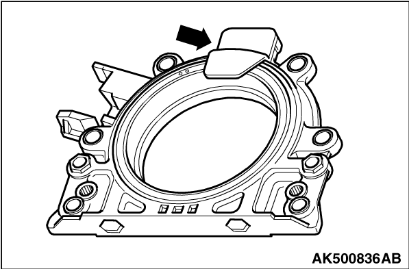
5.Remove securing clip arrow from new sealing flange.
| note |
The sender wheel must not be taken out of the sealing flange or turned.
|
|
|
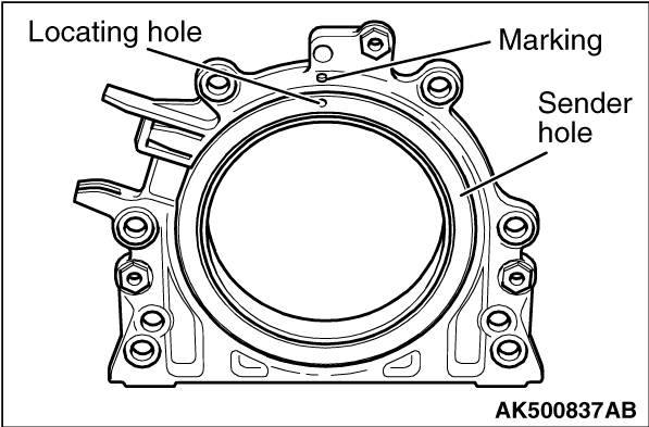
6.Locating hole on sender wheel must align with marking on sealing flange.
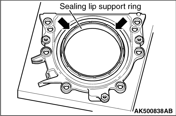
7.Place sealing flange with front side downwards on a clean flat surface.
|
|
8.Push sealing lip support ring downwards in direction of arrow until it lies on flat surface.
|
|
9.Upper edge of sender wheel and front edge of sealing flange must align arrows.
|
|
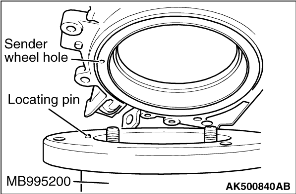
10.Place sealing flange with front side on special tool Oil seal installer (MB995200) that
locating pin can be inserted in sender wheel hole.
| note |
Ensure sealing flange lies flat on special tool Oil seal installer (MB995200).
|
|
|
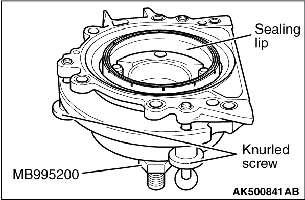
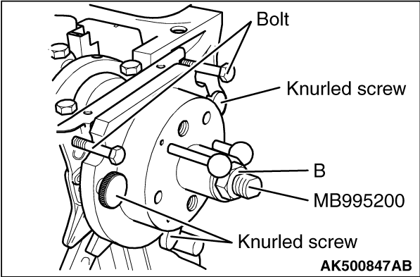
11.Push sealing flange and support ring for sealing lip against surface of special tool Oil
seal installer (MB995200) whilst tightening the three knurled screws so that locating pin cannot
slide out of sender wheel hole.
| note |
- When installing sealing flange, ensure that sender wheel remains fixed in special
tool Oil seal installer (MB995200).
- Crankshaft flange must be free of oil and grease.
- Engine positioned at TDC No.1 cylinder.
|
|
|
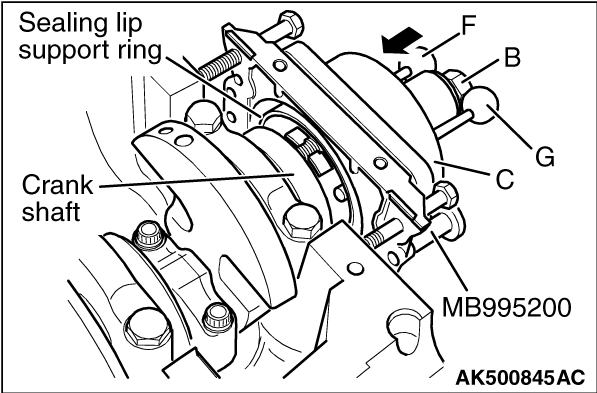
12.Screw hexagon nut "B" to end of threaded spindle.
13.Press threaded spindle of special tool Oil seal installer (MB995200) in direction
of arrow, until hexagon nut "B" lies against assembly bell housing "C."
14.Align flat side of assembly bell housing on sump side of crankcase sealing surface.
|
|
15.Secure special tool Oil seal installer (MB995200) to crankshaft flange using hexagon socket
head bolts "E."
| note |
Screw hexagon socket head bolts "E" into crankshaft flange (approx. 5 full turns).
|
|
|
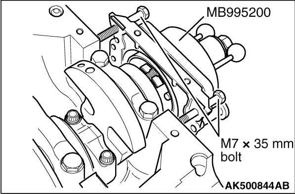
16.To guide sealing flange, screw two M7 × 35 mm bolts into cylinder block.
|
|
17.Push assembly bell housing "C" by hand in direction of arrow.
18.Push guide pin for diesel engines (Black knob) "F" into hole in crankshaft. This ensures
that the sender wheel reaches its final installation position.
| note |
The guide pin for petrol engines (Red knob) "G" must not be inserted in threaded hole
of crankshaft.
|
19.Hand tighten both hexagon socket head bolts of assembly tool.
20.Screw hexagon nut "B" onto threaded spindle by hand until it lies against assembly
bell housing "C."
|
|
21.Tighten hexagon nut of special tool Oil seal installer (MB995200) to the specified torque
of 35 N·m using commercial items.
| note |
After hexagon nut is tightened to the specified torque of 35 N·m torque, a small
air gap must be present between cylinder block and sealing flange.
|
|
|
22.Screw hexagon nut "B" to end of threaded spindle.
23.Remove the two bolts from cylinder block.
24.Screw the three knurled screws out of sealing flange.
25.Remove special tool Oil seal installer (MB995200).
26.Remove sealing lip support ring.
|
|
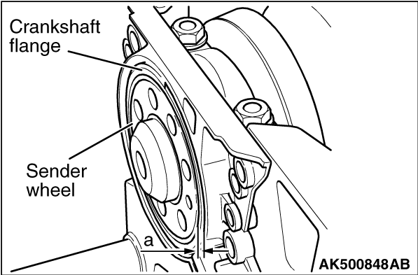
27.The sender wheel is in the correct installation position on the crankshaft if a gap = 0.5
mm exists between crankshaft flange and sender wheel.
|
|
28.Set vernier gauge on crankshaft flange. Measure distance "a" between crankshaft flange
and sender wheel.
|
|
29.If measurement "a" is too small:
Press sender wheel further.
(1)
Secure special tool Oil seal installer (MB995200) to crankshaft flange using hexagon socket
head bolts.
(2)
Hand tighten both hexagon socket head bolts "E."
(3)
Push special tool Oil seal installer (MB995200) by hand to sealing flange.
(4)
Screw hexagon nut "B" onto threaded spindle by hand until it lies against assembly bell
housing.
(5)
Tighten hexagon nut of assembly tool special tool Oil seal installer (MB995200) to the
specified torque of 40 N·m using commercial items.
(6)
Check installation position of sender wheel on crankshaft again.
(7)
If dimension "a" is too small again:
Tighten hexagon nut for special tool Oil seal installer (MB995200) to the specified torque
of 45 N·m.
Check installation position of sender wheel on crankshaft again.
30.If dimension "a" is attained:
Tighten new securing bolts for sealing flange to the specified torque of 15 N·m
using alternate and diagonal sequence.
31.Install intermediate plate.
32.Install flywheel using new bolts, and tighten securing bolts to the specified torque
of 60 N·m +1/4 turn (90°).
|
|
Install crank angle sensor, and tighten securing bolt to the specified torque of 5 N·m.
|
|
|
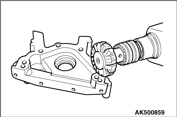
Install intermediate plate to cylinder block.
|
|
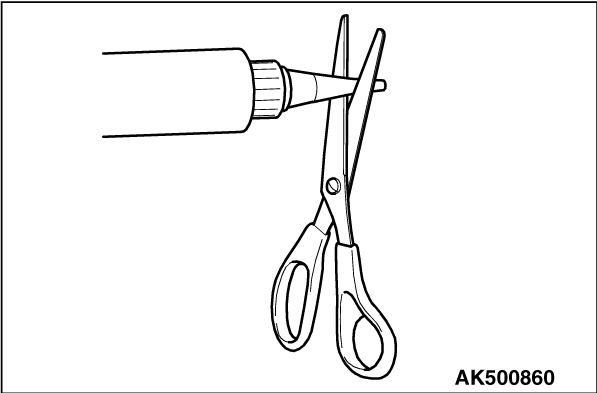
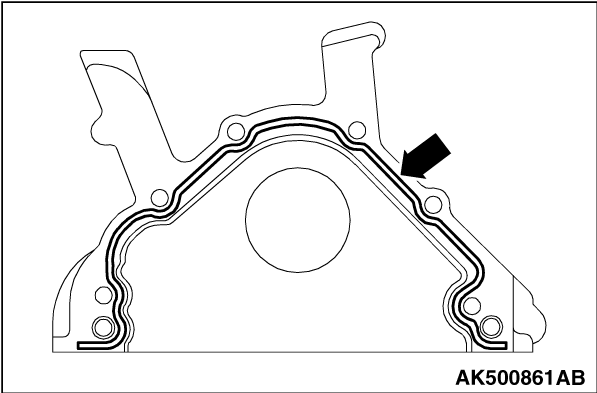
1.Cut off tube nozzle at forward marking (approx. 3 mm diameter of nozzle).
| note |
- Sealant bead must not be wider than 2 to 3 mm, because otherwise excess sealant
can enter sump and clog strainer in oil pump suction pipe as well as drip onto crankshaft oil
seal.
- Before applying sealant bead, cover sealing surface of oil seal with a clean rag.
|
Specified sealant: Mitsubishi Genuine Part No.MD970389
|
|
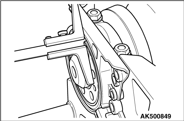
2.Apply silicone sealant bead as shown to the clean sealing surface of sealing flange.
3.Install sealing flange immediately and tighten all bolts lightly.
| note |
When fitting sealing flange with oil seal installed, use special tool Oil seal installer
(MB995222).
|
4.Tighten securing bolts for sealing flange to the specified torque of 15 N·m
using alternate and diagonal sequence.
|
|
|
1.Remove oil residue from end of crankshaft journal using clean cloth.
|
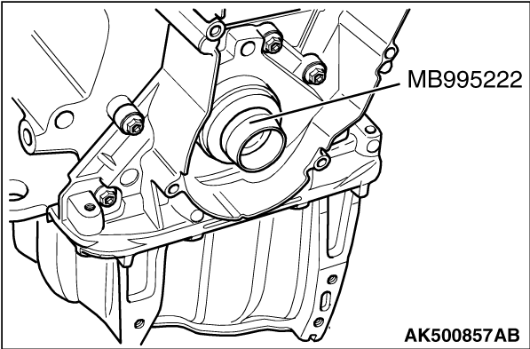
|
2.Place special tool Oil seal installer (MB995222) onto crankshaft journal.
3.Slide oil seal over guide sleeve onto crankshaft journal.
|
|
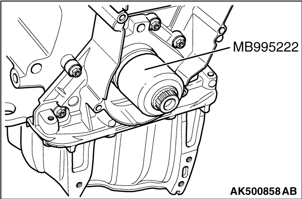
4.Press oil seal in to stop using special tool Oil seal installer (MB995222) and centre
bolt.
|
)

)
)
)
)
)
)
)
)
)
)
)
)
)
)
)
)
)
)
)
)
)
)
)