|
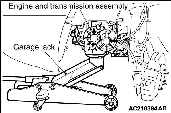
While supporting the engine and transmission assembly with a garage jack, remove the transmission mounting insulator assembly.
|
|
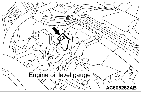
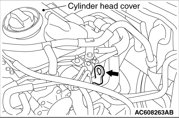
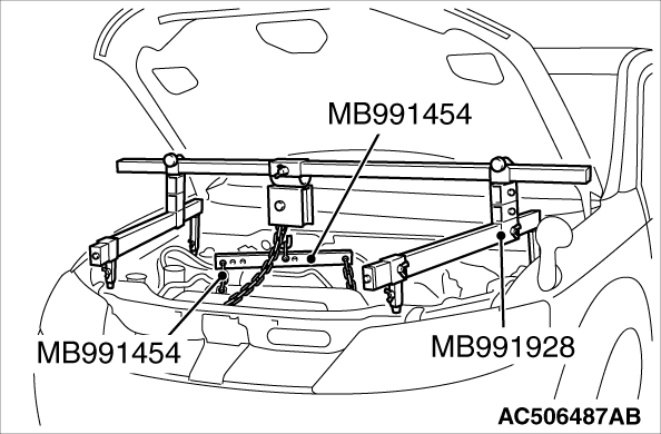
1.Set the engine hanger balancer (special tool: MB991454) to the engine hanger bracket shown in the figure on the left.
|
|
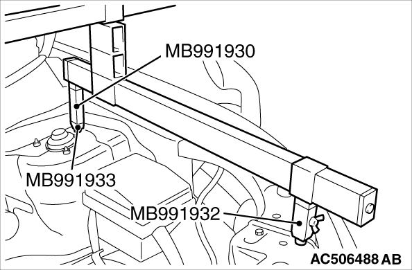
2.<When engine hanger (Special tool: MB991928) is used>
(1)
Assemble the engine hanger (Special tool: MB991928). (Set the components below to the base hanger.)
- Slide bracket (HI)
- Foot x 2 (standard) (MB991932)
- Foot x 2 (short) (MB991933)
- Joint x 2 (90) (MB991930)
(2)
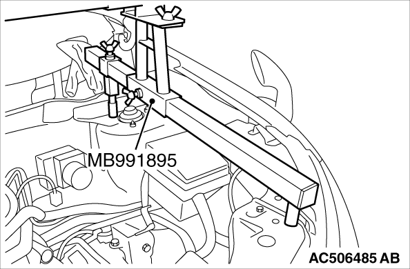
Set the feet of the special tool as shown in the figure.
|
|
| note |
Adjust the engine hanger balance by sliding the slide bracket (HI).
|
|
(3)
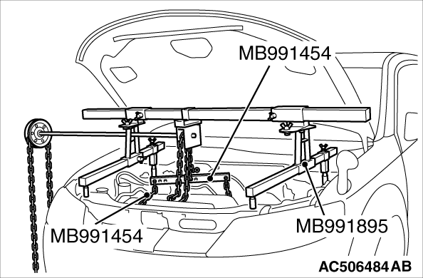
Set the chains of the engine hanger (Special tool: MB991527) and the engine hanger balancer (Special tool: MB991454) to support the engine and transmission assembly. Remove the garage jack and then remove the transmission assembly upper part coupling bolts that have been loosened previously.
|
|
3. <When using engine mechanical hanger (Special tool: MZ203830 or MZ203831)>
(1)
Set the foot of the engine mechanical hanger (Special tool: MZ203830 or MZ203831) as shown in the figure.
|
|
| note |
Slide the front foot of the engine mechanical hanger (Special tool: MZ203830 or MZ203831) to balance the engine hanger.
|
|
|
|
| caution |
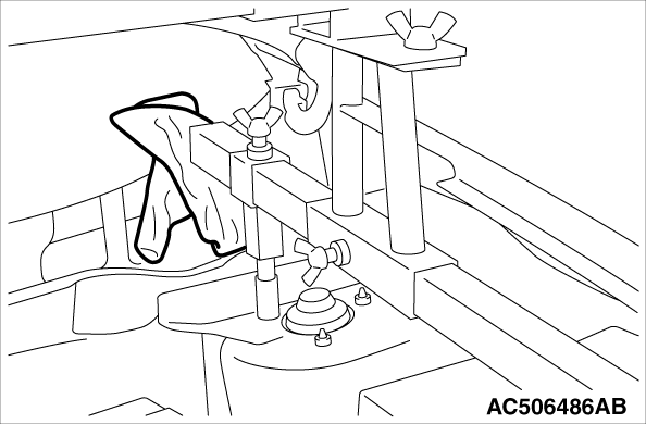
Place rag between the engine mechanical hanger (Special tool: MZ203830 or MZ203831) and the windshield to prevent the special tool from interfering with the windshield.
|
|
(2)
Set the chains of the engine hanger (Special tool: MB991527) and the engine hanger balancer (Special tool: MB991454) to support the engine and transmission assembly. Remove the garage jack and then remove the transmission assembly upper part coupling bolts that have been loosened previously.
|
|
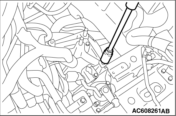
Remove the stud bolt using a commercial stud bolt remover.
|
|
|
Use a tap (pitch: M12 × 1.25) to remove adhesive in the transmission case screw holes, and clean the holes by blowing air.
|
|
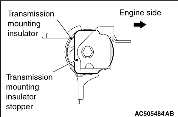
Install the transmission mounting insulator stopper as shown in the figure.
|
 ).
).)
)
)
)
)
)
)
)
)
)
)