
|
1.Remove the shaft snap ring.
|
|
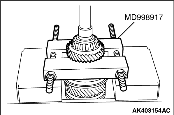
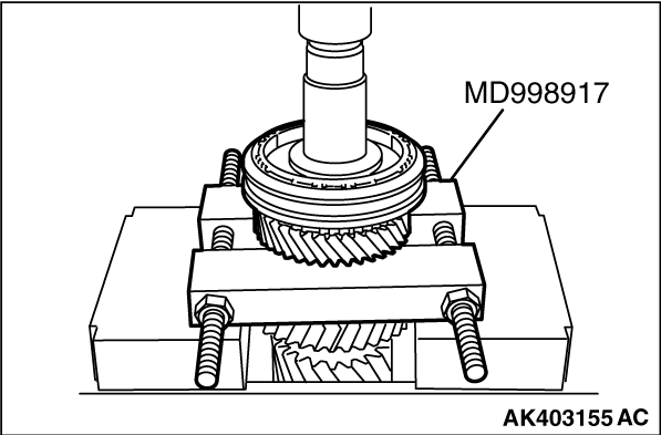
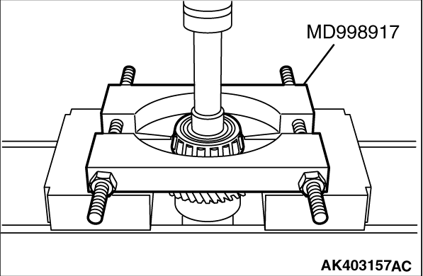
2.Using special tool Bearing remover (MD998917), support the 6th gear sub assembly and remove
the tapered roller bearing #2 and 6th gear sub-assembly.
|
|
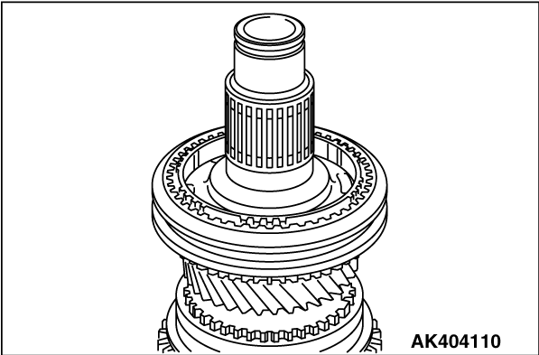
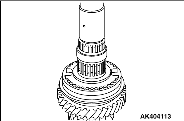
3.Remove the synchronizer outer ring #3.
|
|
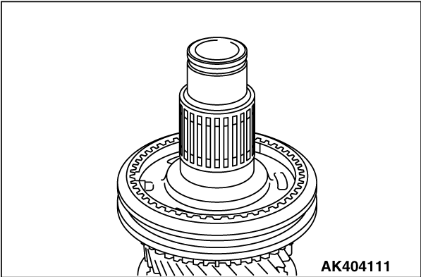
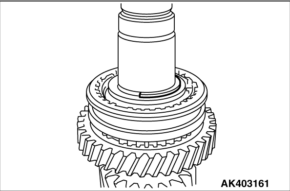
4.Remove the needle roller bearing and spacer.
|
|
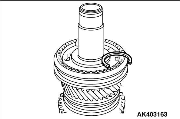
5.Remove the shaft snap ring.
|
|
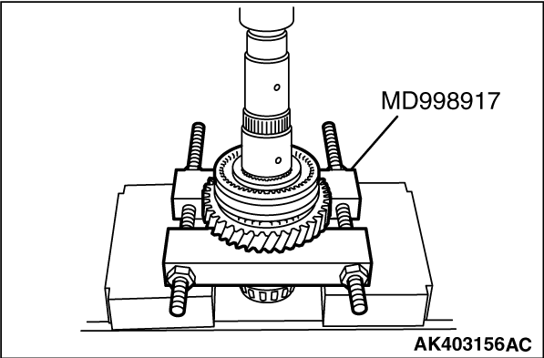
6.Using special tool Bearing remover (MD998917), support the 5th gear sub-assembly and remove
the 5th-6th hub sleeve, synchronizer outer ring #3 and 5th gear sub-assembly.
|
|
7.Remove the spacer and needle roller bearing.
|
|
9.Remove the shaft snap ring.
|
|
10.Using special tool Bearing remover (MD998917), support the reverse gear and remove the
reverse synchronizer sub-assembly, synchronizer ring #4 and reverse gear.
11.Remove the needle roller bearing.
|
|
12.Using special tool Bearing remover (MD998917), support the tapered roller bearing #2
and remove the tapered roller bearing #2.
|
|
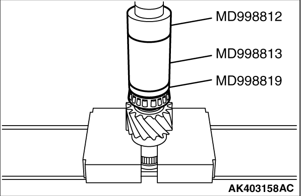
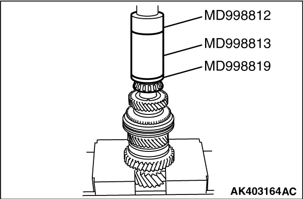
1.Using special tools, install the tapered roller bearing #2.
- Installer cap (MD998812)
- Installer 100 (MD998813)
- Installer adapter (MD998819)
|
|
2.Install the needle roller bearing and reverse gear to output shaft #2.
3.Install the synchronizer ring #4.
|
|
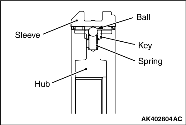
4.As shown in the illustration, install the synchromesh shifting key #3 and the
synchromesh shifting key spring #3.
|
|
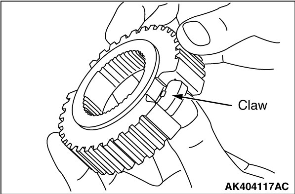
5.Install the synchromesh shifting key #3 to the transmission clutch hub #4
so that the claw is positioned as shown in the illustration.
|
|
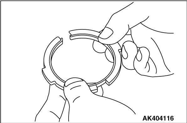
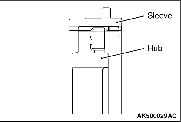
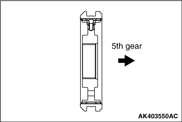
6.Combine the transmission clutch hub #4 with the transmission hub sleeve #4
in the direction as shown in the illustration.
| note |
- Apply gear oil to the caulked area between the sleeve and the hub.
- After installation, confirm the sleeve and the hub slide smoothly.
|
|

|
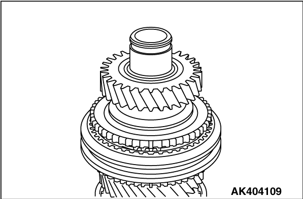
7. Set the reverse synchronizer sub-assembly to the output shaft #2 in the direction
as shown in the illustration.
| note |
- Install the 1st-2nd synchronizer assembly securely into the stopper of the output
shaft #2.
- Check for smooth rotation of the gear after the installation.
|
|
|
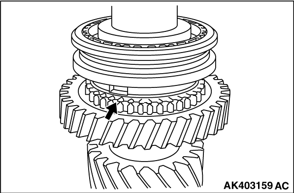
8.Install the synchronizer ring #4, aligning the projection in the synchronizer
hub with the groove in position shown in the illustration.
|
|
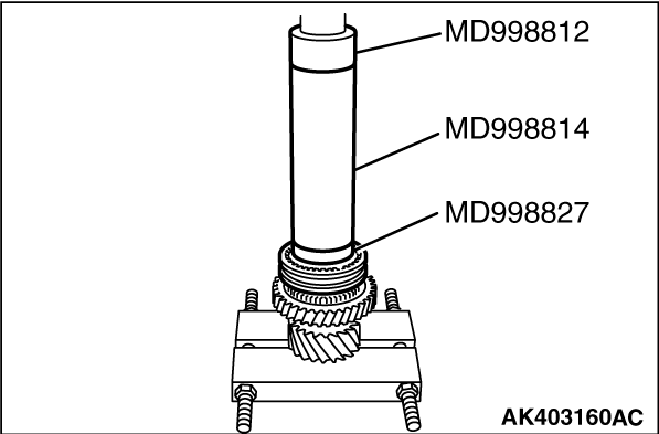
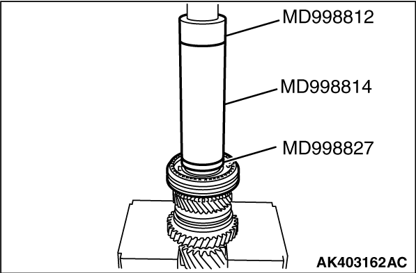
9.Using special tools, install the reverse synchronizer sub-assembly.
- Installer cap (MD998812)
- Installer 200 (MD998814)
- Installer adapter (MD998827)
| note |
- Confirm correct position as shown.
- The synchronizer ring must not bind.
|
|
|
10.Select a shaft snap ring that allows distance of the thrust crevice of reverse hub to
fall within the standard value range.
Standard value: 0 - 0.1 mm
|
|
11.Install the spacer to output shaft #2.
|
|
12.Install the needle roller bearing and spacer to output shaft #2.
|
|
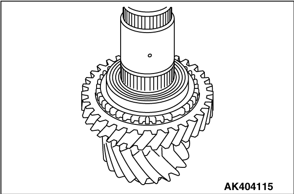
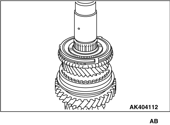
13.Install the 5th gear sub-assembly to output shaft #2, and synchronizer outer
ring #3 to 5th gear sub-assembly.
|
|
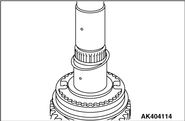
14.As shown in the illustration, set the 5th-6th hub sleeve.
| note |
- Apply gear oil to the caulked area between the sleeve and the hub.
- After the installation, confirm the sleeve and the hub slide smoothly.
|
|
|
15. Set the 5th-6th hub sleeve to the output shaft #2 in the direction as shown
in the illustration.
|
|
16.Using special tools, install the 5th-6th hub sleeve.
- Installer cap (MD998812)
- Installer 200 (MD998814)
- Installer adapter (MD998827)
| note |
- During press fit, confirm correct positions of the hub and the synchronizer ring.
- Install the 5th-6th synchronizer assembly securely into the stopper of the output
shaft #2.
- After installation, confirm the sleeve and the hub slide smoothly.
- The synchronizer ring must not bind.
|
|
|
17.Select a shaft snap ring that allows distance of the thrust crevice of 5th-6th hub to
fall within the standard value range.
Standard value: 0 - 0.1 mm
|
|
18.Install the spacer and needle roller bearing to output shaft #2.
|
|
19.Install the synchronizer outer ring #3 to 5th-6th hub sleeve assembly.
|
|
20.Install the 6th gear sub-assembly to output shaft #2.
|
|
21.Using special tools, install the tapered roller bearing #2.
- Installer cap (MD998812)
- Installer 100 (MD998813)
- Installer adapter (MD998819)
|
|
22.Install the shaft snap ring to output shaft #2.
Standard value: 0 - 0.1 mm
|
)
)
)
)
)
)
)
)
)
)
)
)
)
)
)
)
)
)
)
)
)
)
)
)
)
)