|
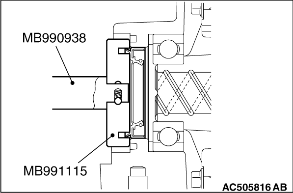
Use the following special tools to press-fit the oil seal:
- Installer bar (MB990938)
- Oil seal installer (MB991115)
|
|
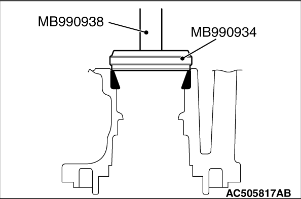
Use the following special tools to press-fit the drive pinion rear bearing outer race:
- Installer adapter (MB990934)
- Installer bar (MB990938)
|
|
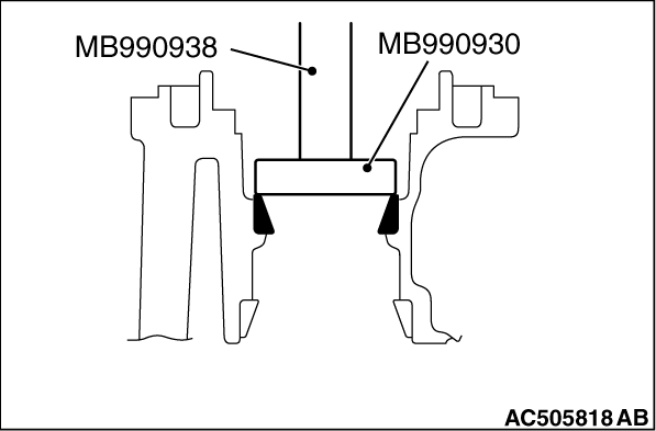
Use the following special tools to press-fit the drive pinion front bearing outer race:
- Installer adapter (MB990930)
- Installer bar (MB990938)
|
|
|
Adjust the drive pinion height in the following steps.
|
|
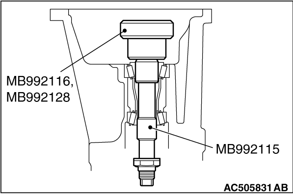
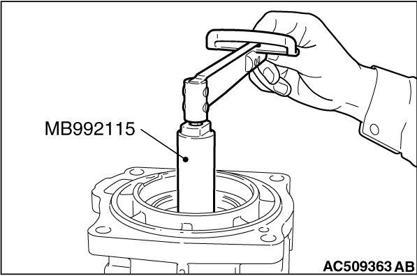
1.Use the following special tools to assemble the drive pinion front and rear bearing inner
laces onto the gear carrier:
- Dummy pinion gauge body (MB992115)
- Dummy pinion gauge head (MB992116)
- Hex socket head bolt (MB992128)
| caution |
The bearing must be free from gear oil.
|
|
|
2.Measure the drive pinion rotation torque.
Standard value:
|
|
Bearing type
|
Bearing lubrication
|
Rotation torque N·m
|
New
|
None
(coated with rust inhibitor oil)
|
0.7 - 1.0
|
|
| note |
After seating the bearing, measure the rotation torque.
|
|
|
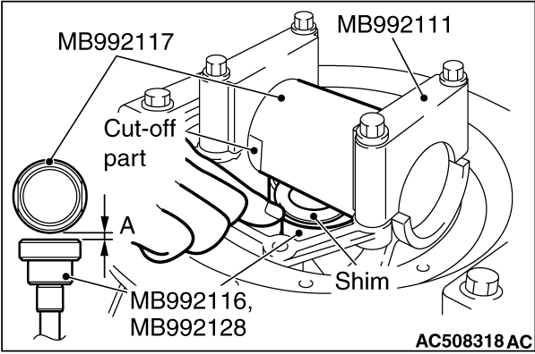
3.Set special tool cylinder gauge (MB992117) on the differential carrier side bearing, and
use special tool side bearing holder (MB992111) to assemble it onto the differential carrier.
Make sure that the cut-off part of the cylinder gauge is positioned as shown in the figure,
and the cylinder gauge is closely contacted with the side bearing.
Tightening torque: 23 ± 3 N·m
4.Select the drive pinion rear shim(s) that corresponds to the gap between the special
tools.
| note |
1. Clean the side bearing.
2. When setting the special tool, make sure that its cut-off part is positioned
as shown in the figure, and it is closely contacted with the side bearing.
3. Try to minimize the number of the drive pinion rear shim(s) to be used.
|
|
|
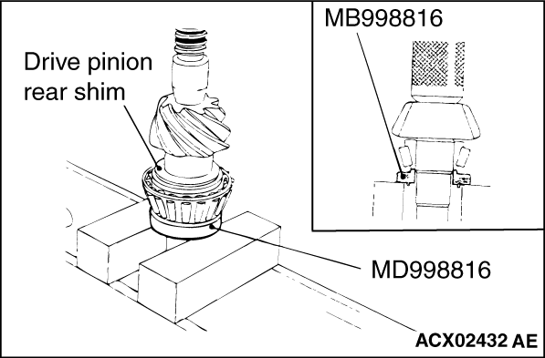
5.Fit the selected drive pinion rear shim(s) onto the drive pinion. Use special tool installer
adapter (MD998816) to press-fit the drive pinion rear bearing inner race.
|
|
|
Adjust the drive pinion rotation torque in the following steps:
|
|
|
1.Insert the drive pinion into the gear carrier. From rear side of the carrier, assemble
the drive pinion spacer, drive pinion front shim and drive pinion front bearing inner race.
| note |
Do not assemble the oil seal.
|
|
|
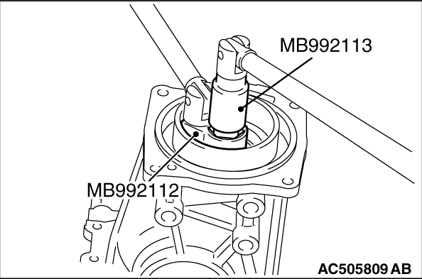
2.Use the following special tools to tighten the differential nut to the specified torque:
- Locking nut wrench (MB992112)
- Drive pinion holder (MB992113)
3.Rotate the drive pinion several turns, and then measure the drive pinion rotation
torque.
Standard value:
|
|
Bearing type
|
Bearing lubrication
|
Rotation torque N·m
|
New
|
None
(coated with rust inhibitor oil)
|
0.7 - 1.0
|
|
|
|
4.When the rotation torque is not within the standard value range, adjust the torque
by selecting the drive pinion front shim(s).
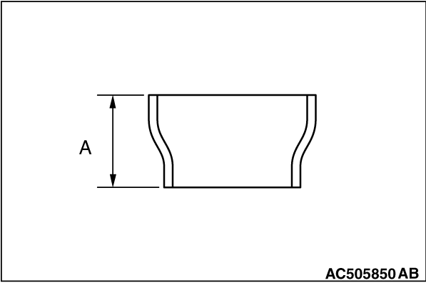
| note |
When selecting the drive pinion front shim(s), select the drive pinion spacer to minimize
the number of the shims to be used. There are two drive pinion spacers available:
|
|
|
Drive pinion spacer height A mm
|
24.3
|
23.6
|
|
|
|
5.Use the following special tools to tighten the differential nut to the specified torque:
- Locking nut wrench (MB992112)
- Drive pinion holder (MB992113)
Tightening truque :190 ± 30 N·m
|
|
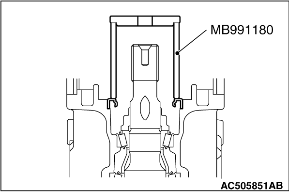
6.Use special tool bushing remover and installer base (MB991180) to press-fit the oil seal.
7.Rotate the drive pinion several turns, and then measure the drive pinion rotation
torque.
Standard value:
|
|
Bearing type
|
Companion flange lubrication
|
Rotation torque N·m
|
New
|
None (coated with rust inhibitor oil)
|
0.7 - 1.0
|
|
8.When the rotation torque is not within the standard value, check the differential
locking nut tightening torque or the oil seal assembly condition.
|
|
|
Adjust the differential gear backlash in the following steps.
|
|
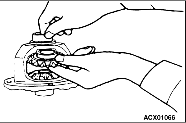
1.Assemble the side gear, side gear spacer, pinion gear and pinion washer into the differential
case.
2.Temporarily assemble the pinion shaft.
| note |
Do not assemble the lock pin at this stage.
|
|
|
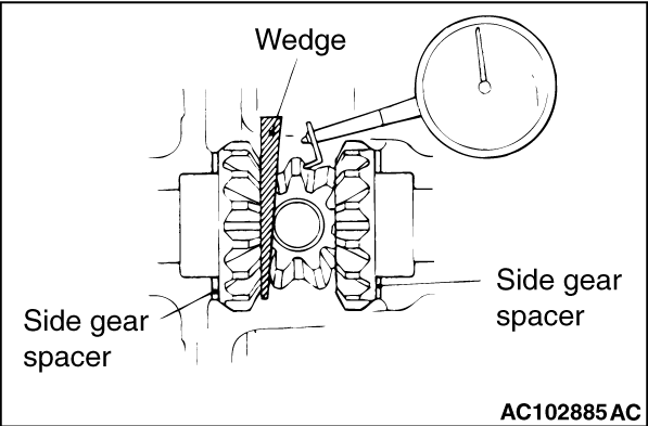
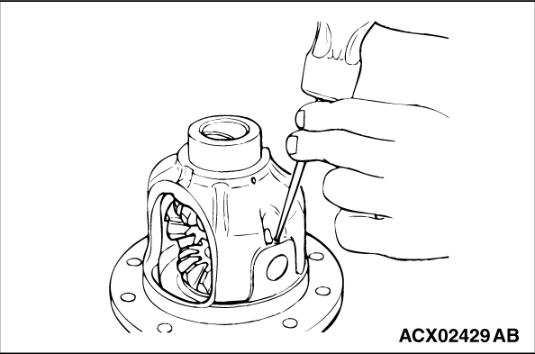
3.Drive a wooden wedge between one of the side gears and the pinion shaft to fix the side
gear.
4.Set a dial gauge (with the measuring rod extended) against the pinion gear and measure
the backlash. Repeat the same procedure to measure the backlash at the other pinion gear.
Standard value: 0 to 0.076 mm
Limit : 0.2 mm
5.When the backlash exceeds the limit, adjust it by selecting the side gear spacer.
6.When the adjustment is not possible, replace the side gear and the pinion gear as
a set.
7.After the adjustments, make sure that the backlash is within the limit and the differential
gear rotates smoothly.
|
|
1.Align the lock pin holes in the pinion shaft and in the differential case, and drive in
the lock pin.
2.Use a punch to crimp two points.
|
|
|
1.Remove adhesive on the drive gear tightening bolts.
|
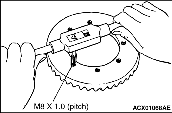
|
2.Use a tap to remove adhesive in the drive gear screw holes, and clean the holes by blowing
air.
|
|
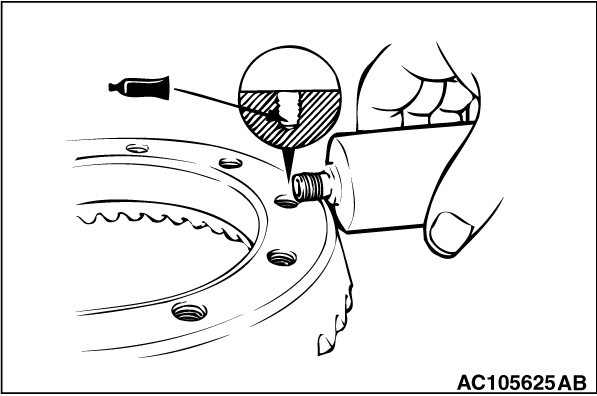
3.Apply the specified thread locking compound in the drive gear screw holes.
Specified sealant: LOCTITE No.271 or No.270 or equivalent
4.Align the mating marks and assemble the drive gear to the differential case.
Tightening torque: 41 ± 5 N·m
|
|
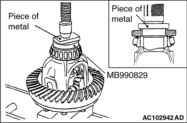
Use special tool pinion and side bearing installer (MB990829) to press-fit the differential
side bearing inner race.
|
|
|
Adjust the final drive gear backlash in the following steps:
|
|
|
1.To the gear carrier, install the differential case with the side bearing outer race
assembled.
|
|
2.Press the differential case to one side, and measure clearance between the side bearing
outer race and the gear carrier.
3.Select two pairs of the side bearing spacers. (Thickness: 1/2 of the measured
clearance with 0.05-mm preload added)
|
|
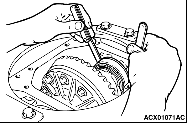
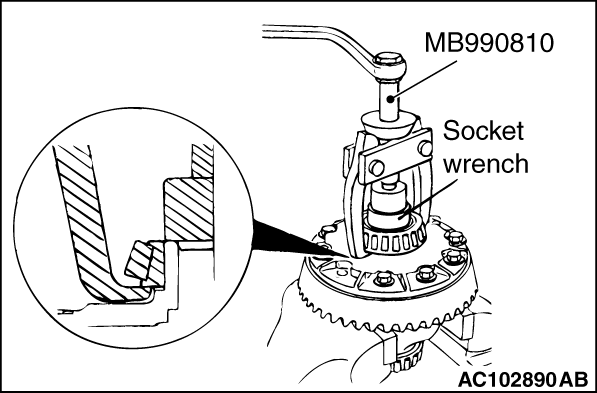
4.Use special tool side bearing puller (MB990810) to remove the side bearing.
| note |
Hook the claws of the special tool on the side bearing inner race through two cut-off
parts in the differential case.
|
5.Assemble the selected side bearing spacers on both sides.
|
|
6.Use special tool pinion and side bearing installer (MB990829) to press-fit the side bearing
inner race into the differential case and install the outer race.
|
|
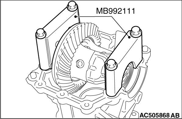
7.Use special tool side bearing holder (MB992111) to install the differential case to the
differential carrier.
Tightening torque: 23 ± 3 N·m
|
|
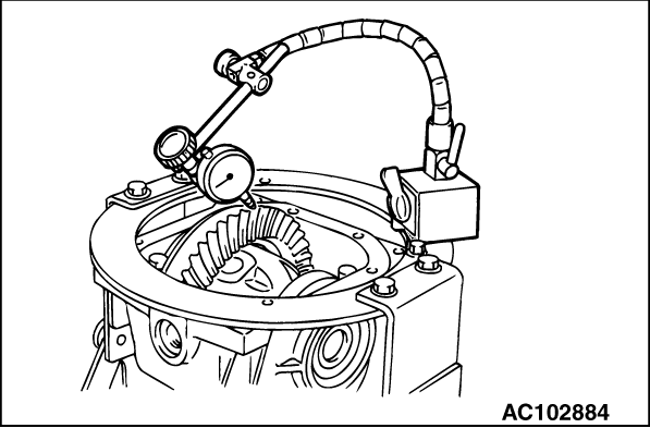
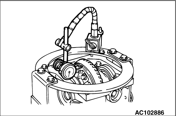
8.Measure the final drive gear backlash at four or more points.
Standard value: 0.10 to 0.15 mm
|
|
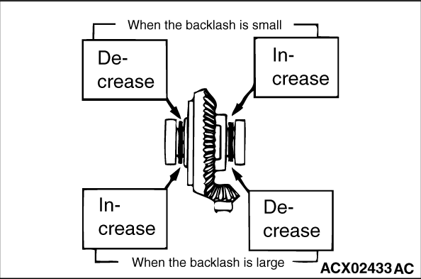
9.When the backlash is not within the standard value range, move the side bearing spacers
as shown in the figure to adjust the backlash.
| note |
Increase the side bearing spacers by the same amount as for the decrease.
|
10.Check the final drive gear teeth contact, and if not proper, adjust it(Refer to  ). ).
|
|
11.Measure the drive gear runout on the backside.
Limit : 0.05 mm
12.When the runout exceeds the limit, change position of the drive gear and differential
case, and measure the runout again.
13.If the adjustment is not possible, replace the differential case or the drive gear
and the drive pinion as a set.
|
)
)
)
)
)
)
)
)
)
)
)
)
)
)
)
)
)
)
)
)
)
)
)
)