|
|
1.Pass the brake hose through the hole in the body-side bracket.
|
|
|
2.Install the brake hose to the brake caliper.
|
|
|
3.Install the brake hose at the two fixing points.
|
|
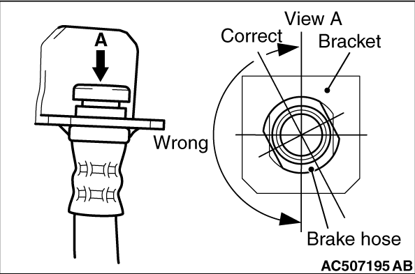
4.Twist the brake hose toward the lesser torsion between the brake hose and body-side bracket
as shown in the figure, and fix it to the body-side bracket with a clip.
|
|
|
Measure the brake drag force in the following procedure:
|
|
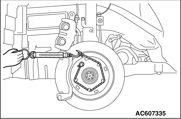
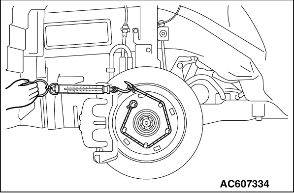
1.Using a spring scale, measure the hub sliding torque in the forward direction.
|
|
2.
| caution |
Keep grease or other soiling off the pad and brake disc
friction surfaces.
|
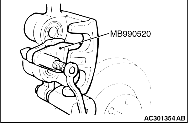
Clean the piston, and press the piston into the cylinder using special tool piston expander
(MB990520).
3.Assemble the pad clip and pad to the caliper support, and tighten the guide pin to
the specified torque.
Tightening torque: 45 ±
5 N·m
4.Start the engine, and depress the brake pedal forcibly two or three times. Then, stop
the engine.
5.Turn the brake disc 10 times in the forward direction.
|
|
6.Using a spring scale, measure the hub sliding torque in the forward direction.
7.Obtain the disc brake drag force (difference between measured values of item 1 and
item 6).
Standard value: 68 N or less
8.If the brake drag force exceeds the standard value, disassemble the piston to check
for fouling/rust on the piston sliding section and piston/seal deterioration,
and confirm whether the slide pin slides properly.
|
 ).
).)
)
)
)
)