|
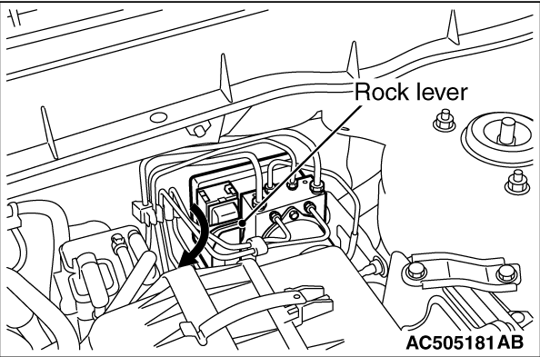
1.Operate the lock lever to disconnect the ABS-ECU harness connector as shown in the figure.
|
|
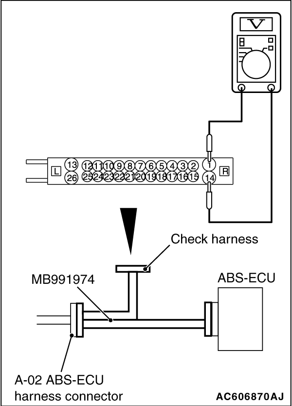
2.Connect the special tool ABS check harness (MB991974) to measure the voltage between each
check connector terminal and the earth terminal (No. 1 or 14).
Terminal No.
|
Check item
|
Check conditions
|
Normal conditions
|
7
|
ABS-ECU power supply
|
Ignition switch: ON
|
Approximately battery voltage
|
Ignition switch: OFF
|
0V
|
13
|
Motor power supply
|
Ignition switch: ON (OFF)
|
Approximately battery voltage
|
16
|
Wheel speed sensor (RR) power supply
|
Ignition switch: ON
|
Approximately battery voltage
|
18
|
Wheel speed sensor (FL) power supply
|
Ignition switch: ON
|
Approximately battery voltage
|
22
|
Wheel speed sensor (FR) power supply
|
Ignition switch: ON
|
Approximately battery voltage
|
24
|
Wheel speed sensor (RL) power supply
|
Ignition switch: ON
|
Approximately battery voltage
|
26
|
Solenoid valve power supply
|
Ignition switch: ON (OFF)
|
Approximately battery voltage
|
|
|
1.Operate the lock lever to disconnect the ABS-ECU harness connector as shown in the figure.
|
|
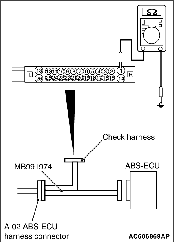
2.When performing the continuity check, turn the ignition switch to "LOCK" (OFF) position,
connect the special tool ABS check harness (MB991974) as shown in the figure, and disconnect
the ABS-ECU connector.
3.Check the continuity between terminals shown in the chart below.
4.Terminal layout is shown in the figure.
Terminal No.
|
Signal
|
Normal conditions
|
1 - body earth
|
Earth
|
Continuity exists (2 Ω or less)
|
14 - body earth
|
Earth
|
Continuity exists (2 Ω or less)
|
|
)
)
)