|
|
- ABS-ECU contains the power supply circuit (terminal No. 13) for the pump
motor. The pump motor is energised by the motor switch, which is incorporated in ABS-ECU.
- The pump motor switch, which is incorporated in ABS-ECU, is always off unless the
motor solenoid valve check is activated when the vehicle is started.
- ABS-ECU activates the pump motor by turning on the ECU built-in pump motor switch.
|
|
|
If the pump motor switch voltage drop indicates high value when the pump motor operates
or after the operation, the pump motor operation is stopped and this diagnosis code is set.
|
|
|
Current trouble
- Fusible link malfunction
- Damaged wiring harness and connectors
- Abnormality in battery or alternator
- ABS-ECU malfunction
|
|
|
Past trouble
- Carry out diagnosis with particular emphasis on wiring harness and
connector failures between the power supply circuit (A-02 ABS-ECU connector terminal No. 13)
to the ABS-ECU motor and the earth circuit (A-02 ABS-ECU connector terminal No. 1). For diagnosis
procedures, refer to How to treat past trouble (GROUP 00 - How to Cope with Intermittent
Malfunction
 ). ).
|
|
|
Use M.U.T.-III to diagnose the CAN bus lines.
|
|
|
Q.
Is the check result normal?
|
|
|
 Repair the CAN bus lines (Refer to GROUP 54C - CAN Bus Diagnosis table ).
On completion, go to Step 2. Repair the CAN bus lines (Refer to GROUP 54C - CAN Bus Diagnosis table ).
On completion, go to Step 2.
|
|
|
|
|
|
Q.
Is the diagnosis code No. C1073 set?
|
|
|
This diagnosis is complete.
|
|
|
|
|
|
Q.
Is the check result normal?
|
|
|
Replace the fusible link No. 26.
|
|
|
|
|
|
Refer to GROUP 54A - Battery Test .
|
|
|
Q.
Is the battery in good condition?
|
|
|
Charge or replace the battery.
|
|
|
|
|
|
Refer to GROUP 16 - Charging System .
|
|
|
Q.
Is the charging system in good condition?
|
|
|
Repair or replace the charging system component(s).
|
|
|
|
|
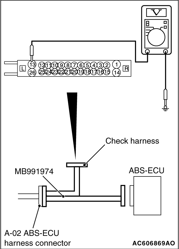
(1)Disconnect the ABS-ECU connector, connect special tool ABS check harness (MB991974) to
the harness-side connector, and then measure the resistance at the special tool connector side.
| note |
Do not connect the special tool ABS check harness (MB991974) to ABS-ECU.
|
(2)Turn the ignition switch to the ON position.
(3)Measure the voltage between the terminal No. 13 and the body earth.
OK: Battery voltage
Q.
Is the check result normal?
 Go to Step 8. Go to Step 8.
Go to Step 7.
|
|
|
Q.
Is the check result normal?
|
|
|
The open or short circuit may be present in the solenoid valve power supply circuit.
Repair the wiring harness between the A-02 ABS-ECU connector terminal No. 13 and the fusible
link No. 26.
|
|
|
|
|
|
NO : Repair the defective connector.
|
|
|
|
|
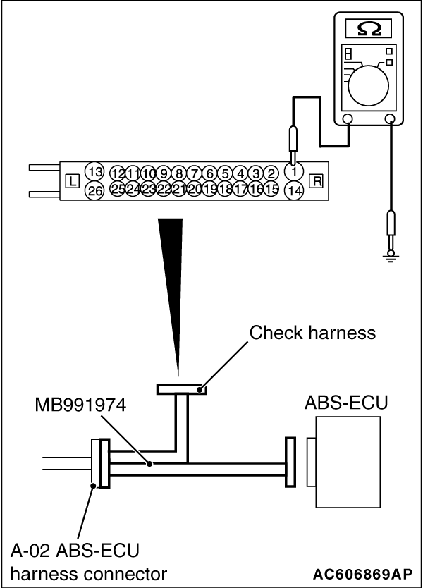
(1)Disconnect the ABS-ECU connector, connect special tool ABS check harness (MB991974) to
the harness-side connector, and then measure the resistance at the special tool connector side.
| note |
Do not connect the special tool ABS check harness (MB991974) to ABS-ECU.
|
(2)Resistance between the terminal No. 1 and the body earth
OK: Continuity exists (2 Ω or less)
Q.
Is the check result normal?
Go to Step 10.
Go to Step 9.
|
|
|
Q.
Is the check result normal?
|
|
|
An open circuit may be present in the earth circuit. Repair the wiring harness
between the A-02 ABS-ECU terminal No. 1 and the body earth.
|
|
|
|
|
|
NO : Repair the defective connector.
|
|
|
|
|
|
- Drive the vehicle at 20 km/h or more.
|
|
|
Q.
Is the diagnosis code No. C1073 set?
|
|
|
Intermittent malfunction (Refer to GROUP 00 - How to Cope with Intermittent
Malfunction ).
|
|
|
|
)
)
)
)
)