|
|
The hydraulic sensor is incorporated in the hydraulic unit. When the brake pedal is depressed,
the pressure sensor detects the brake pressure applied from the master cylinder, converts this
pressure into the voltage signal, and outputs it.
|
|
|
This diagnosis codes will be set under the cases below:
|
|
|
- When the pressure sensor offset is not within the standard value range
- When the estimated pressure sensor temperature is not normal
|
|
|
- Incorrect adjustment of brake pedal height
- Master cylinder malfunction
- Brake booster malfunction
- Incorrect installation position of stop lamp switch
- Malfunction of the stop lamp switch
- Brake drag
- ASC-ECU malfunction
|
|
|
Use M.U.T.-III to diagnose the CAN bus lines.
|
|
|
Q.
Is the check result normal?
|
|
|
 Repair the CAN bus lines (Refer to GROUP 54C - Troubleshooting Repair the CAN bus lines (Refer to GROUP 54C - Troubleshooting  ).
On completion, go to Step 2. ).
On completion, go to Step 2.
|
|
|
|
|
|
Q.
Is the diagnosis code No. C121E set?
|
|
|
This diagnosis is complete.
|
|
|
|
|
|
Refer to GROUP 35A - On-vehicle Service .
|
|
|
Q.
Is the check result normal?
|
|
|
Adjust the brake pedal, and then go to Step 4.
|
|
|
|
|
|
Refer to GROUP 35A - On-vehicle Service .
|
|
|
Q.
Is the check result normal?
|
|
|
Install the stop lamp switch correctly, and then go to Step 5.
|
|
|
|
|
|
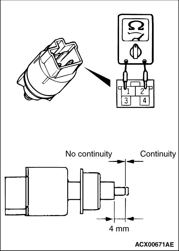
(1)Remove the stop lamp switch. (Refer to GROUP 35A -Brake Pedal .)
|
|
(2)Connect the circuit tester (Ω range) to the stop lamp switch connector terminals
No. 1 and 2.
(3)When no continuity is detected with the plunger pressed from the edge of the outer
case by the dimension shown in the figure and when continuity is detected with the plunger released,
the stop lamp switch is in good condition.
Q.
Is the check result normal?
 Go to Step 6. Go to Step 6.
Replace the stop lamp switch, and then go to Step 6.
|
|
|
Check the brake system for drag.
|
|
|
Q.
Is the check result normal?
|
|
|
Refer to GROUP 35A - On-vehicle Service .
|
|
|
Q.
Is the check result normal?
|
|
|
Replace the brake booster.
|
|
|
|
|
|
Q.
Is the diagnosis code No. C121E set?
|
|
|
This diagnosis is complete.
|
|
|
|
)