REMOVAL AND INSTALLATION


caution
  • Before removing the steering wheel and airbag module, refer to GROUP 52B - Service Precautions and Airbag Module and Clock Spring . Position the front wheels in a straight ahead direction. If you fail to do this, clock spring for SRS may get damage not to operate the SRS (air bag), and it may cause the serious injury of the driver.
  • *The bolts and nuts marked with * are coated with the friction coefficient stabilizer. When removed these parts, make sure that they are free of damage, remove any dust and dirt on the bearing surfaces and the threads, and tighten to the specified torque.
Pre-removal operation
  • Power Steering Fluid Draining (Refer to .)
  • Steering Wheel Assembly and Air Bag Module Removal (Refer to .)
  • Footrest and Steering Shaft Cover Removal (Refer to .)
  • Under Cover Removal (Refer to GROUP 51 - Exterior and Under Cover .)
  • Front Height Sensor Removal (Refer to GROUP 54A - Chassis Electrical, Headlamp Auto Levelling System and Height Sensor .)
  • Centre Member Removal (Refer to GROUP 32 - Engine Roll Stopper and Centre Member .)

Post-installation operation
  • Centre Member Installation (Refer to GROUP 32 - Engine Roll Stopper and Centre Member .)
  • Front Height Sensor Installation (Refer to GROUP 54A - Chassis Electrical, Headlamp Auto Levelling System and Height Sensor .)
  • Under Cover Removal (Refer to GROUP 51 - Exterior and Under Cover .)
  • Using your fingers, press the dust cover of each joint to check for a crack or damage.
  • Footrest and Steering Shaft Cover Installation (Refer to .)
  • Steering Wheel Assembly and Air Bag Module Installation (Refer to .)
  • Power Steering Fluid Refilling and Bleeding (Refer to .)
  • Steering wheel straight-ahead position check
  • Wheel Alignment Check and Adjustment (Refer to GROUP 33, On-vehicle Service - Front Wheel Alignment Check and Adjustment .)


Removal steps


1.
Steering gear and joint connecting bolt
<<A>>

2.
Self-lock nut (Tie-rod end and knuckle connection)


3.
Lower arm and knuckle connection


4.
Stabiliser link


5.
Lower arm assembly


6.
Eye bolt


7.
Gasket


8.
Pressure hose connection


9.
Return hose connection


10.
Return tube assembly


11.
Flanged nut


12.
Engine rear roll stopper bracket connecting bolt
<<B>>

13.
Front axle No.1 crossmember assembly


14.
Engine rear roll stopper


15.
Heat protector

>>A<<
16.
Joint cover grommet


17.
Flanged bolt


18.
Steering gear and linkage

REMOVAL SERVICE POINTS


<<A>> SELF-LOCK NUT (TIE-ROD END AND KNUCKLE CONNECTION) REMOVAL


1.
caution
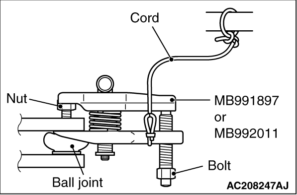
  • Loosen the self-lock nut (tie-rod end and knuckle connection) from the ball joint (Do not remove). Use the special tool for the self-lock nut removal.
  • To prevent the special tool from dropping off, suspend it with a rope.
Install the ball joint remover (Special tool MB991897 or MB992011) as shown in the figure.

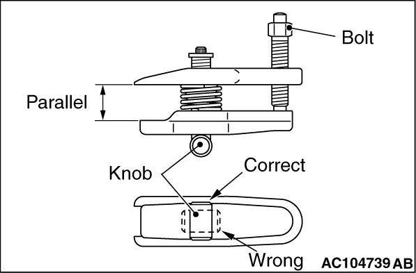
2.Turn the bolt and knob to make the special tool jaws parallel, then hand-tighten the bolt. After tightening, check that the jaws are still parallel.
note To adjust the special tool jaws to be parallel, set the orientation of the knob as shown in the figure.
3.Unscrew the bolt to disconnect the ball joint.

<<B>> FRONT AXLE NO.1 CROSSMEMBER ASSEMBLY REMOVAL


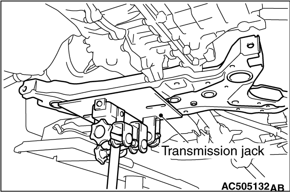
1.Jack up and support the crossmember, and remove it.
2.Check the hoses and harnesses for roughness, and then remove the front axle No.1 crossmember assembly with the rear roll stopper and the steering gear and linkage installed.

INSTALLATION SERVICE POINTS


>>A<< JOINT COVER GROMMET INSTALLATION


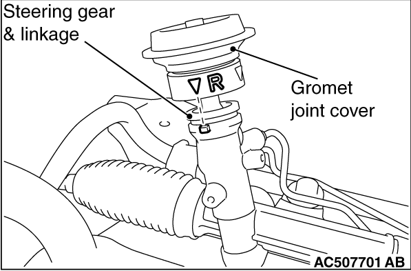
Install the joint cover grommet to the steering gear and linkage by aligning the mating marks as shown in the figure.