|
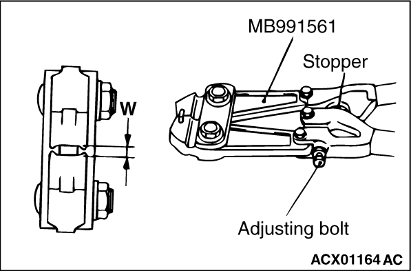
1.Turn the adjusting bolt for the special tool boot band clipping tool (MB991561) to
adjust the opening dimension (W) to the standard value.
Standard value (W): 2.9 mm
<When opening dimension is more than 2.9 mm>
Tighten the adjusting bolt.
<When opening dimension is less than 2.9 mm>
Loosen the adjusting bolt.
| note |
- The adjusting bolt changes W approximately 0.7 mm for each rotation.
- Do not rotate the adjusting bolt more than one rotation.
|
|
|
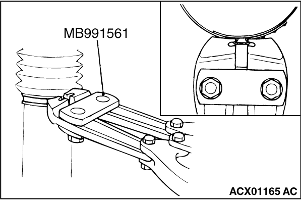
2.
| caution |
- Secure the gear housing, and crimp the crimping part of the band firmly with the tip of
the special tool.
- Crimp the boot band securely until the special tool contacts the stopper.
|
Use the special tool to crimp the boot band.
|
|
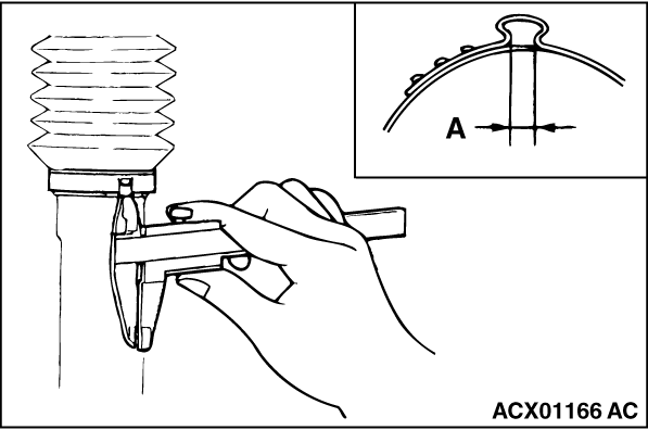
3.Check that the crimping width of the boot band (A) is within the range of the standard
value.
Standard value (A): 2.4 - 2.8 mm
<When the crimping width is greater than 2.8 mm>
Readjust the value W described in Step 1 to the following formula, and perform the operation
in Step 2 again.
W=5.5-A (Example: When A is 2.9, W is 2.6.)
<When the crimping width is less than 2.4 mm>
Remove the boot band, readjust the value W described in Step 1 to the following formula,
and perform the Steps 2 and 3 using a new boot band.
W=5.5-A (Example: When A is 2.3, W is 3.2.)
|
|
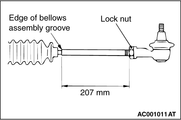
Screw in the tie-rod to the length shown in the figure, and hand-tighten the locking nut.
| note |
Install the steering gear & linkage to the body, adjust the toe-in, and then
tighten the locking nut to the specified torque.
|
|
)

)
)
)
)
)