|
|
Remove the knob cap while pressing the two projections.
|
|
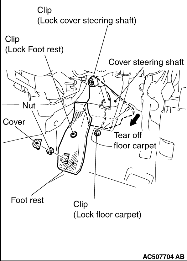
1.Release the cover, nut, and clip (for securing the footrest), and remove the foot rest.
2.Remove the clip (for securing the floor carpet), and turn over the floor carpet.
3.Remove the clip (for securing the steering shaft cover), and then remove the steering
shaft cover.
|
|
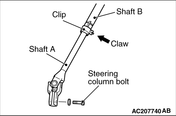
1.Remove the steering column bolt connecting the steering gear to the steering column assembly.
2.Disconnect the steering gear from the steering column assembly while sliding the shaft
A to the shaft B with the clip claw as shown in the figure is pinched.
3.Remove the steering column mounting bolt.
|
|
|
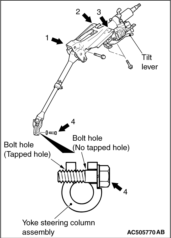
1.Ensure that the tilt lever is in the lock position, and install the
steering column as below.
|
|
2.Hand-tighten the mounting bolts in the order of 1, 2, 3, and tighten them in the order
of 3, 2, 1 to the specified torque.
Tightening torque:
Mounting bolt 1: 28 ± 7 N·m
Mounting bolt 2, 3: 12 ± 3 N·m
3.Assemble the steering column assembly to the steering gear.
4.Insert the bolt connecting the steering column assembly with the steering gear into
the non-threaded bolt hole.
5.Tighten the mounting bolt 4 to the specified torque.
Tightening torque: 20 ± 5 N·m
|
|
1.
| caution |
If the centre of the clock spring is not correctly aligned,
the steering wheel may not be turned fully or the cable inside the clock spring may be broken,
causing the SRS air bag to be inoperative or operated incorrectly.
|
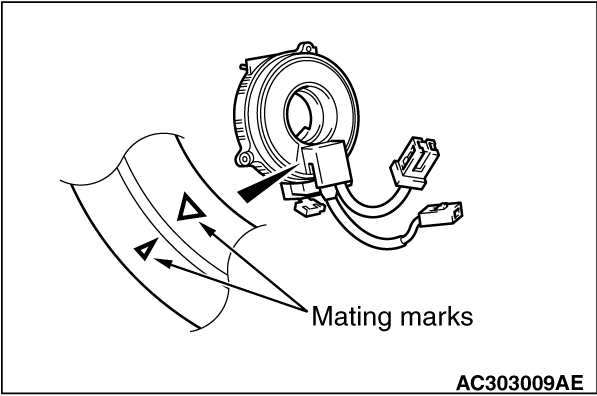
Align the mating marks of the clock spring.
<Alignment of mating marks>
(1)
Turn the clock spring clockwise fully.
(2)
Turn the clock spring counterclockwise approximately three and 3/4 turns
to align the mating marks.
(3)
Install the clock spring to the column switch.
|
|
2.
| caution |
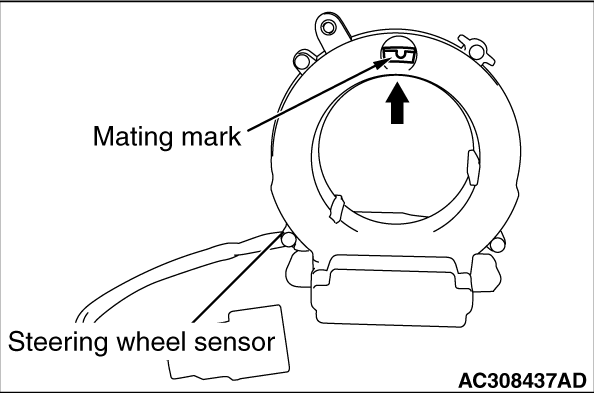
Be sure to align the steering wheel sensor neutral position mark. If the neutral
position marks are not aligned, the steering wheel operation may damage the steering wheel sensor.
|
Align the steering wheel sensor neutral position mark. <Vehicles with ASC>
<Alignment of mating marks>
(1)
When checking the neutral position check window of the steering wheel sensor, if an
arrow can be seen, turn to the direction of the arrow, and align the neutral position mark as
shown in the figure.
(2)
Install the steering wheel sensor to the column switch assembly, maintaining the neutral
position correctly.
(3)
Install the column switch assembly to the vehicle, maintaining the neutral position
correctly.
|
 and
Air Bag Module Clock Spring
and
Air Bag Module Clock Spring )
)
)
)
)
)