Inspection Procedure
4: Check the WCM power supply and earth circuits.
|
|
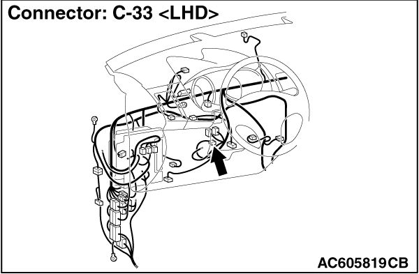
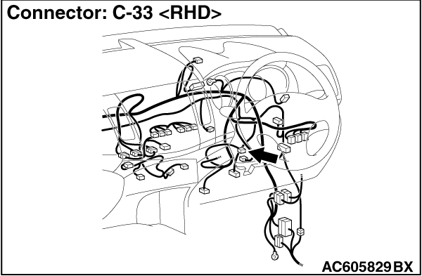
STEP 1. Connector check: C-33 WCM connector
|
|
|
Q.
Is the check result normal?
|
|
|
 Go to Step 2. Go to Step 2.
|
|
|
|
|
|
 Repair the defective connector. Repair the defective connector.
|
|
|
|
|
|
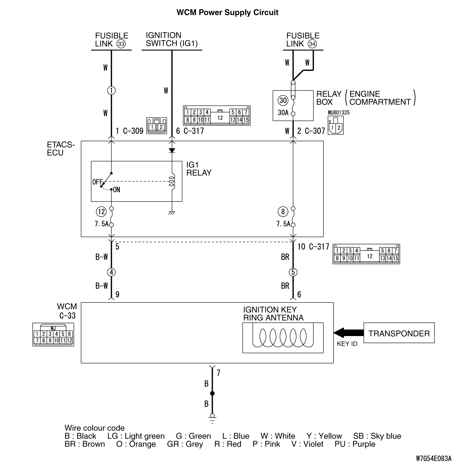
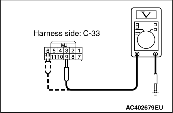
STEP 2. Voltage measurement at the C-33 WCM connector.
|
|
|
(1)Disconnect the connector and measure the resistance at the wiring harness side.
|
|
|
(2)Turn the ignition switch to the ON position.
|
|
(3)Measure the voltage between the C-33 WCM connector terminals No. 6/9, and the
body earth.
OK: Battery voltage
Q.
Is the check result normal?
Go to Step 4.
Go to Step 3.
|
|
|
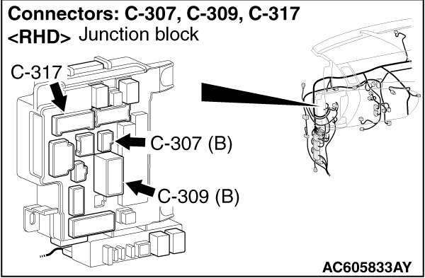
STEP 3. Check the wiring harnesses between the C-33 WCM connector
terminal No. 6, 9 and the fusible link (36, 34).
|
|
|
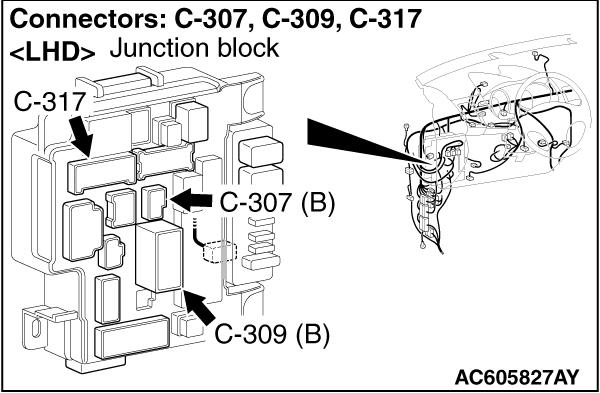
| note |
Before checking the wiring harnesses, check the joint connectors C-307, C-309, and C-317,
and repair if necessary.
|
|
|
|
- Check the power supply line for open circuit.
|
|
|
Q.
Is the check result normal?
|
|
|
Go to Step 4.
|
|
|
|
|
|
Repair the wiring harness.
|
|
|
|
|
|
STEP 4. Resistance measurement at the C-33 WCM connector.
|
|
|
(1)Disconnect the connector and measure the resistance at the wiring harness side.
|
|
|
(2)Turn the ignition switch to the ON position.
|
|
|
(3)Measure the resistance between the C-33 WCM connector terminal No. 7 and the body
earth.
OK: Continuity exists (2 Ω
or less)
|
|
|
Q.
Is the check result normal?
|
|
|
The diagnosis is complete.
|
|
|
|
|
|
Go to Step 5.
|
|
|
|
|
|
STEP 5. Check the wiring harness between the C-33 WCM connector terminal
No. 7 and the body earth.
|
|
|
- Check the earth wires for open circuit.
|
|
|
Q.
Is the check result normal?
|
|
|
The diagnosis is complete.
|
|
|
|
|
|
Repair the wiring harness.
|
|
|
|
)
)
)
)
)
)