INSPECTION PROCEDURE
C-1: Power Windows do not work at All.
| caution |
Before replacing the ECU,
ensure that the power supply circuit, the earth circuit and the communication circuit are normal.
|
COMMENTS ON TROUBLE SYMPTOM
If the power windows do not work at all, a malfunction of the power window main switch
or ETACS-ECU is suspected.
PROBABLE CAUSES
- Malfunction of the power window main switch
- Malfunction of ETACS-ECU
- Damaged wiring harness and connectors
DIAGNOSTIC PROCEDURE
STEP 1. Check the power supply system.
With the ignition switch in the LOCK (OFF) position, check if the following function operates
normally:
Q.
Is the check result normal?
 Go to Step 2.
 Refer to GROUP 54A -
malfunction of ETACS-ECU power supply circuit
Refer to GROUP 54A -
malfunction of ETACS-ECU power supply circuit  .
.
STEP 2. M.U.T.-III diagnosis code
Check that ETACS-ECU sets a diagnosis code.
Q.
Is the diagnosis code set?
Refer to GROUP 54B -
Troubleshooting .
Go to Step 3.
STEP 3. M.U.T.-III data list
Check the signals related to the power window operation.
|
|
Item No.
|
Item name
|
Normal condition
|
254
|
IG Voltage
|
Battery voltage
|
|
OK: Normal condition is displayed.
Q.
Is the check result normal?
Go to Step 4.
Refer to GROUP 54A -
inspection procedure 2: the ignition switch (IG1)
signal is not received .
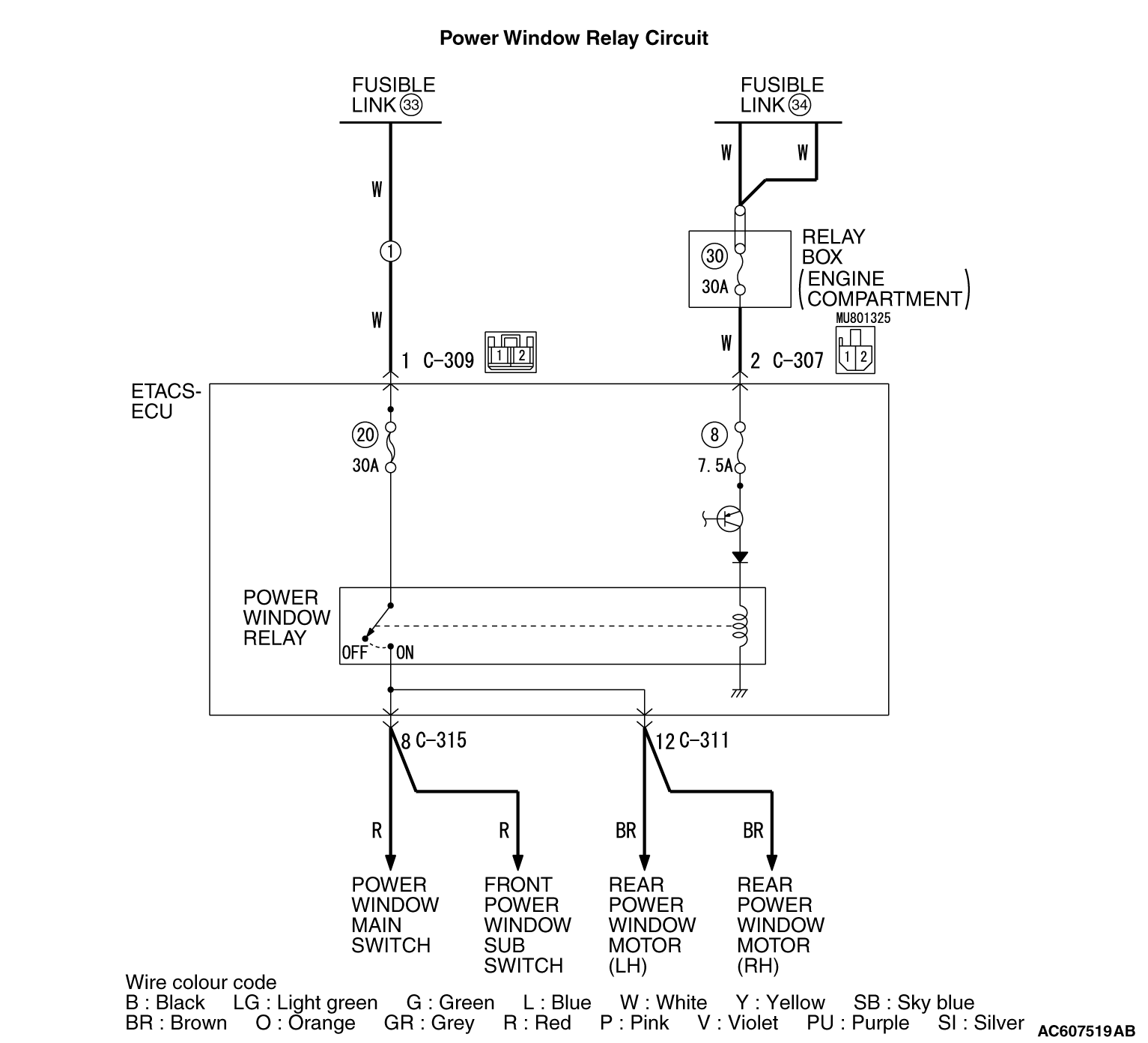
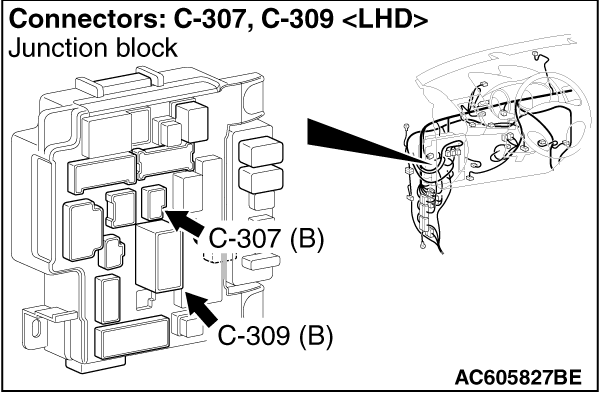
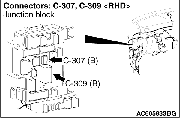
STEP 4. Connector check: C-309 ETACS-ECU connector
Q.
Is the check result normal?
Go to Step 5.
Repair the defective connector.
STEP 5. Voltage measurement at the C-309 ETACS-ECU connector
|
|
(1)Disconnect the connector, and measure at the wiring harness side.
|
|
|
(2)Measure the voltage between the C-309 ETACS-ECU connector terminal No. 1 and the
body earth.
OK: Battery voltage
|
Q.
Is the check result normal?
Go to Step 7.
Go to Step 6.
STEP 6. Check of the wiring harness between the C-309 ETACS-ECU connector
terminal No. 1 and the fusible link (33).
- Check the power supply line for open circuit.
Q.
Is the check result normal?
Intermittent malfunction (Refer to GROUP 00 -
How to Use Troubleshooting/Inspection
Service Points -
How to Cope with Intermittent Malfunction ).
Repair the wiring harness.
STEP 7. Connector check: C-307 ETACS-ECU connector
Q.
Is the check result normal?
Go to Step 8.
Repair the defective connector.
STEP 8. Voltage measurement at the C-307 ETACS-ECU connector.
|
|
(1)Disconnect the connector, and measure at the wiring harness side.
|
|
|
(2)Measure the voltage between the C-307 ETACS-ECU connector terminal No. 2 and the
body earth.
OK: Battery voltage
|
Q.
Is the check result normal?
Go to Step 10.
Go to Step 9.
STEP 9. Check the wiring harness between C-307 ETACS-ECU connector
terminal No. 2 and fusible link (34).
Q.
Is the check result normal?
Intermittent malfunction (Refer to GROUP 00 -
How to Use Troubleshooting/Inspection
Service Points -
How to Cope with Intermittent Malfunction ).
Repair the wiring harness.
STEP 10. Retest the system.
Check that the all the power windows work.
Q.
Is the check result normal?
Intermittent malfunction (Refer to GROUP 00 -
How to Use Troubleshooting/Inspection
Service Points -
How to Cope with Intermittent Malfunction ).
Replace ETACS-ECU.
)
)
)