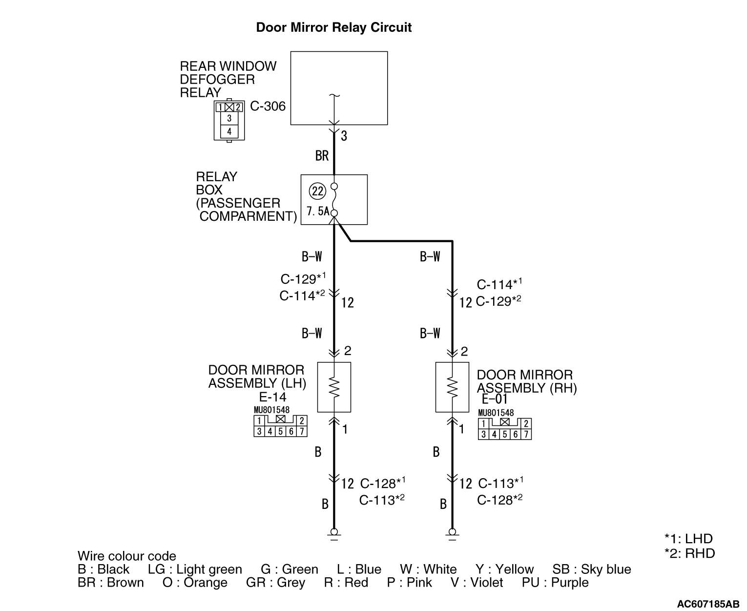
INSPECTION PROCEDURE
8: Either of the door mirror heater elements does not work.
|
|
COMMENTS ON TROUBLE SYMPTOM
|
|
|
If either of the door mirror heater elements does not work, the power supply or earth
to the element, or the element itself may be defective.
|
|
|
- Door mirror heater elements failed
- Wiring harness or connector failure
|
|
|
STEP 1. Determine a trouble spot.
|
|
|
Q.
Which of door mirror heater elements does not work?
|
|
|
Driver’s door mirror : Go to Step 2. : Go to Step 2.
|
|
|
|
|
|
Passenger’s door mirror : Go to Step 9.
|
|
|
|
|
|
STEP 2. Check of the heater element of the door mirror (RH)
|
|
|
Check the heater element of the door mirror (RH). (Refer to Heater Element Check  .) .)
|
|
|
Q.
Is the check result normal?
|
|
|
 Go to Step 3. Go to Step 3.
|
|
|
|
|
|
 Replace the mirror glass of the door mirror assembly (RH). Replace the mirror glass of the door mirror assembly (RH).
|
|
|
|
|
|
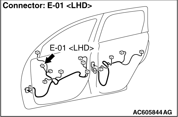
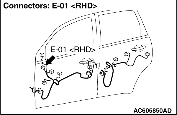
STEP 3. Check the E-01 door mirror assembly (RH) connector
|
|
|
Q.
Is the check result normal?
|
|
|
Go to Step 4.
|
|
|
|
|
|
Repair the defective connector.
|
|
|
|
|
|
STEP 4. Measure the resistance at the E-01 door mirror assembly (RH)
connector.
|
|
|
(1)Disconnect the connector, and measure at the wiring harness side.
|
|
|
(2)Resistance between E-01 door mirror assembly (RH) connector terminal No. 1 and
body earth
OK: Continuity (2 Ω or less)
|
|
|
Q.
Is the check result normal?
|
|
|
Go to Step 6.
|
|
|
|
|
|
Go to Step 5.
|
|
|
|
|
|
STEP 5. Check the wiring harness between E-01 door mirror assembly
(RH) connector terminal No. 2 and body earth.
|
|
|
| note |
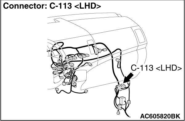
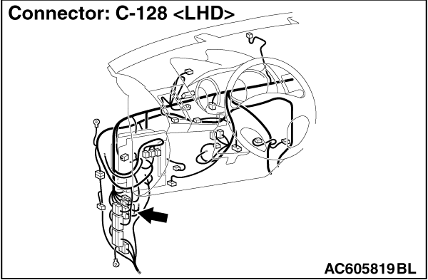
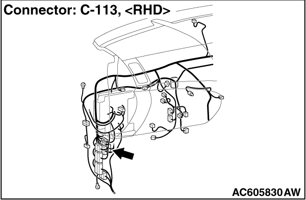
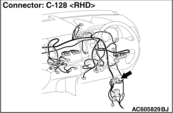
Prior to the wiring harness inspection, check intermediate connector C-128 <LHD> or
C-113 <RHD>, and repair if necessary.
|
|
|
|
- Check the earth wires for open circuit.
|
|
|
Q.
Is the check result normal?
|
|
|
Intermittent malfunction (Refer to GROUP 00 - How to Use Troubleshooting/Inspection
Service Points - How to Cope with Intermittent Malfunction ).
|
|
|
|
|
|
Repair the wiring harness.
|
|
|
|
|
|
STEP 6. Measure the voltage at the E-01 door mirror assembly (RH)
connector.
|
|
|
(1)Turn the ignition switch to the ON position.
|
|
|
(2)Turn on the rear window defogger switch.
|
|
|
(3)Disconnect the connector, and measure at the wiring harness side.
|
|
|
(4)Measure the voltage between E-01 door mirror assembly (RH) connector terminal No.
1 and body earth.
OK: Battery voltage
|
|
|
Q.
Is the check result normal?
|
|
|
Intermittent malfunction (Refer to GROUP 00 - How to Use Troubleshooting/Inspection
Service Points - How to Cope with Intermittent Malfunction ).
|
|
|
|
|
|
Go to Step 7.
|
|
|
|
|
|
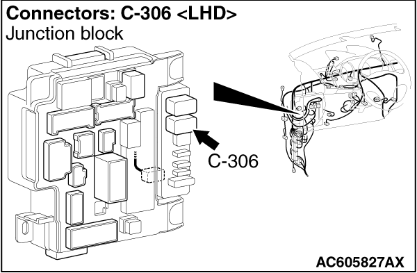
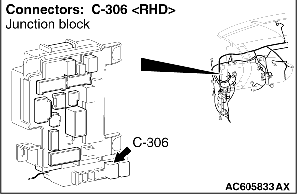
STEP 7. Check the wiring harness between E-01 door mirror assembly
(RH) connector terminal No. 2 and C-306 rear window defogger relay connector terminal No. 3.
|
|
|
| note |
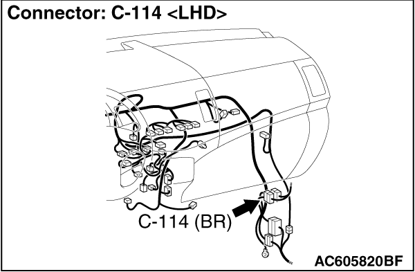
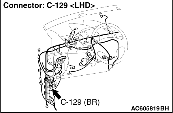
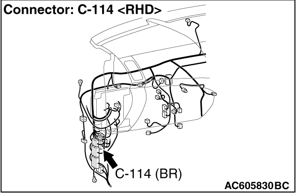
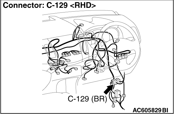
Prior to the wiring harness inspection, check intermediate connector C-114 <LHD> or
C-129 <RHD>, and repair if necessary.
|
|
|
|
- Check the power supply line for open circuit.
|
|
|
Q.
Is the check result normal?
|
|
|
Go to Step 8.
|
|
|
|
|
|
Repair the wiring harness.
|
|
|
|
|
|
STEP 8. Retest the system.
|
|
|
Check that the heater element of the door mirror (RH) functions normally.
|
|
|
Q.
Is the check result normal?
|
|
|
Intermittent malfunction (Refer to GROUP 00 - How to Use Troubleshooting/Inspection
Service Points - How to Cope with Intermittent Malfunction ).
|
|
|
|
|
|
Replace the door mirror assembly (RH).
|
|
|
|
|
|
STEP 9. Check of the heater element of the door mirror (LH)
|
|
|
Check the heater element of the door mirror (LH). (Refer to Heater Element Check .)
|
|
|
Q.
Is the check result normal?
|
|
|
Go to Step 10.
|
|
|
|
|
|
Replace the mirror glass of the door mirror assembly (LH).
|
|
|
|
|
|
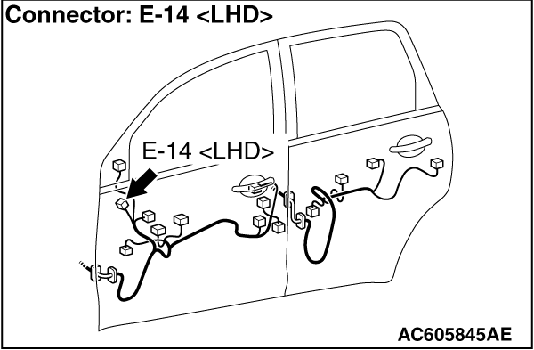
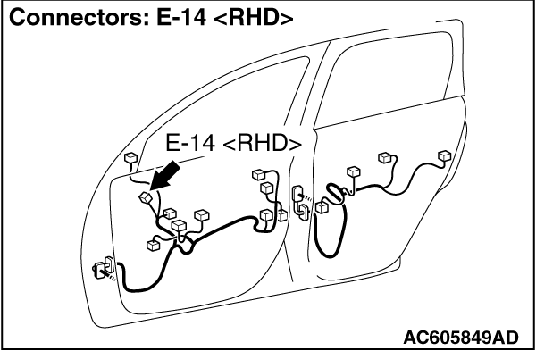
STEP 10. Check the E-14 door mirror assembly (LH) connector
|
|
|
Q.
Is the check result normal?
|
|
|
Go to Step 11.
|
|
|
|
|
|
Repair the defective connector.
|
|
|
|
|
|
STEP 11. Measure the resistance at the E-14 door mirror assembly (LH)
connector.
|
|
|
(1)Disconnect the connector, and measure at the wiring harness side.
|
|
|
(2)Measure the resistance between E-14 door mirror assembly (LH) connector terminal
No. 1 and body earth.
OK: Continuity(2 Ω or less)
|
|
|
Q.
Is the check result normal?
|
|
|
Go to Step 13.
|
|
|
|
|
|
Go to Step 12.
|
|
|
|
|
|
STEP 12. Check the wiring harness between E-14 door mirror assembly
(LH) connector terminal No. 2 and body earth.
|
|
|
| note |
Prior to the wiring harness inspection, check intermediate connector C-128 <LHD> or
C-113 <RHD>, and repair if necessary.
|
|
|
|
- Check the earth wires for open circuit.
|
|
|
Q.
Is the check result normal?
|
|
|
Intermittent malfunction (Refer to GROUP 00 - How to Use Troubleshooting/Inspection
Service Points - How to Cope with Intermittent Malfunction ).
|
|
|
|
|
|
Repair the wiring harness.
|
|
|
|
|
|
STEP 13. Measure the voltage at the E-14 door mirror assembly (LH)
connector.
|
|
|
(1)Turn the ignition switch to the ON position.
|
|
|
(2)Turn on the rear window defogger switch.
|
|
|
(3)Disconnect the connector, and measure at the wiring harness side.
|
|
|
(4)Voltage between E-14 door mirror assembly (LH) connector terminal No. 1 and body
earth.
OK: Battery voltage
|
|
|
Q.
Is the check result normal?
|
|
|
Intermittent malfunction (Refer to GROUP 00 - How to Use Troubleshooting/Inspection
Service Points - How to Cope with Intermittent Malfunction ).
|
|
|
|
|
|
Go to Step 14.
|
|
|
|
|
|
STEP 14. Check the wiring harness between E-14 door mirror assembly
(LH) connector terminal No. 2 and C-306 rear window defogger relay connector terminal No. 3.
|
|
|
| note |
Prior to the wiring harness inspection, check intermediate connector C-129 <LHD> or
C-114 <RHD>, and repair if necessary.
|
|
|
|
- Check the power supply line for open circuit.
|
|
|
Q.
Is the check result normal?
|
|
|
Go to Step 15.
|
|
|
|
|
|
Repair the wiring harness.
|
|
|
|
|
|
STEP 15. Retest the system.
|
|
|
Check that the heater element works normally.
|
|
|
Q.
Is the check result normal?
|
|
|
Intermittent malfunction (Refer to GROUP 00 - How to Use Troubleshooting/Inspection
Service Points - How to Cope with Intermittent Malfunction ).
|
|
|
|
|
|
Replace the door mirror assembly (LH).
|
|
|
|
)
)
)
)
)
)
)
)
)
)
)
)
)
)
)