REMOVAL AND INSTALLATION


caution
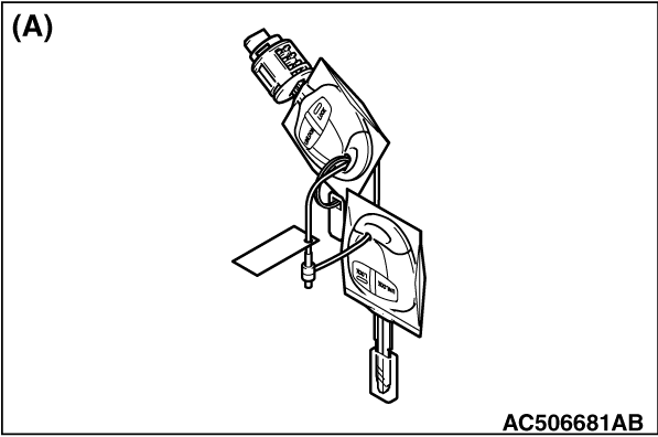
  • When a supply unit of glove box lock cylinder shown in the illustration (A) is replaced, do not register a transponder ID using the bar code which is attached to the ignition key supplied simultaneously. If the transponder ID is registered with the attached bar code, the engine cannot 
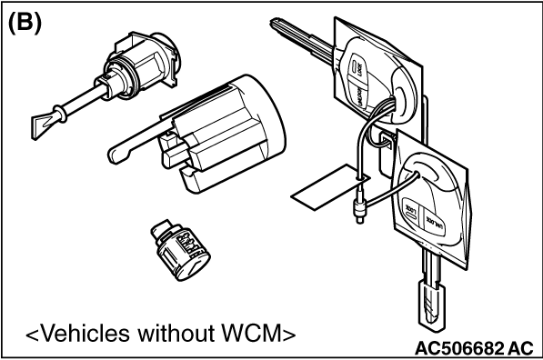
start. However, only for vehicles without WCM, when one ignition key is used both for lock cylinder and engine start-up, it is necessary to replace a key set shown in the illustration (B).
  • When a key set in the illustration (B) is replaced, always register the transponder ID.

The following bolts and screws are used for installing the instrument panel: The bolts and screws are indicated by symbols in the illustrations in sections "REMOVAL AND INSTALLATION" and "DISASSEMBLY AND ASSEMBLY."
Name
Symbol
Dimensions mm (screw diameter × screw length)
Colour
Shape
Tapping screw
a
5 × 12
-


b
5 × 16
-
c
5 × 12
Black


d
5 × 14
-
e
5 × 16
-
f
5 × 16
Black
g
5 × 20
-
Washer-assembled bolt
h
6 × 16
-


caution
  • For the removal of the front passenger’s air bag module, refer to GROUP 52B - Service Precautions , Driver’s and Front Passenger’s Air Bag Module, and Clock Spring before operation.
  • Do not subject SRS-ECU to any shocks when removing or installing the instrument panel.


Removal steps


1.
Steering column upper cover


2.
Steering column lower cover


3.
Ignition key cover


4.
Cup holder assembly


5.
Side box


6.
Centre air outlet


7.
Centre panel assembly


8.
Centre panel box <Vehicles with audio> or 6 disc CD autochanger & AM/FM radio


9.
Bottom cover assembly (driver’s side)


10.
Bottom cover assembly (passenger’s side)


·
Glove box lamp connector


11.
Glove box assembly


12.
Glove box lock cylinder


13.
Glove box dumper


14.
Side air outlet


15.
Combination meter bezel


16.
Combination meter assembly


17.
Side lower panel assembly


·
Lower side cover (Refer to ).


18.
Centre lower panel


19
A/C control panel


20.
Side cover


21.
Glove box side panel


22.
Centre upper box assembly


23.
Upper glove box assembly


·
Steering wheel (Refer to GROUP 37 - Steering Wheel ).


24.
Solar sensor


25.
Instrument panel assembly

CLIP AND CLAW POSITIONS


note Each number in the illustration indicates a part number.