REMOVAL AND INSTALLATION


caution
  • Disconnect the negative (-) battery terminal and wait for 60 seconds or more before starting work. Insulate the disconnected (-)terminal by wrapping the tape (Refer to the item 5 of Service Precautions ).
  • Never attempt to disassemble or repair the air bag modules and clock spring. If faulty, replace it with new one(s).
  • Do not drop the air bag modules or clock spring or allow contact with water, grease or oil. If denting, cracking, or deformation is discovered, replace it with new one(s).
  • Store the air bag modules on a flat surface with the deployment surface facing up. Also, do not put anything on it.
  • Do not store the air bag modules in a place more than 93°C.
  • When the driver’s and passenger’s (front) air bags have been deployed, replace the driver’s and passenger’s (front) air bag modules with new ones. Also, check the clock spring, and replace with a new part if there is an abnormality.
  • Put on gloves and safety glasses when handling deployed air bags.
  • When discarding the air bag module, make sure to deploy the air bag before the disposal (Refer to ).

<DRIVER’S AIR BAG MODULE AND CLOCK SPRING>


Pre-removal operation
  • Disconnect the negative (-) battery terminal.

caution After the installation, perform a calibration for the ASC-ECU to learn the steering wheel sensor neutral point <Vehicle with ASC>.


Driver’s air bag module removal steps
<<A>>

1.
Cover


2.
Horn connector connection
<<B>>

3.
Driver’s air bag module connector connection
<<C>>

4.
Driver’s air bag module


Driver’s air bag module installation steps

>>A<<
·
Pre-installation inspection

>>C<<
4.
Driver’s air bag module

>>D<<
3.
Driver’s air bag module connector connection

>>D<<
2.
Horn connector connection


1.
Cover

>>E<<
·
Post-installation inspection


Clock spring removal steps
<<A>>

1.
Cover


2.
Horn connector connection
<<B>>

3.
Driver’s air bag module connector connection
<<C>>

4.
Driver’s air bag module
<<D>>

5.
Steering wheel assembly


·
Lower, upper column cover (Refer to GROUP 37 - Steering shaft ).
<<E>>

6.
Clock spring


Clock spring installation steps

>>A<<

Pre-installation inspection

>>B<<
6.
Clock spring


·
Lower, upper column cover (Refer to GROUP 37 - Steering shaft ).

>>C<<
5.
Steering wheel assembly

>>C<<
4.
Driver’s air bag module

>>D<<
3.
Driver’s air bag module connector connection

>>D<<
2.
Horn connector connection


1.
Cover

>>E<<
·
Post-installation inspection


·
Steering wheel sensor calibration (Refer to GROUP 35C - On-vehicle Service - Steering Wheel Sensor Calibration ) <Vehicles with ASC>.

<Passenger’s (front) air bag module>


Pre-removal operation
  • Turn ignition switch to the LOCK (OFF) position.
  • Disconnect the negative (-) battery terminal.


Passenger’s (front) air bag module removal steps
<<F>>

1.
Passenger’s (front) air bag module connector connection


·
Instrument panel assembly (Refer to GROUP 52A - Instrument Panel Assembly ).
<<G>>

2.
Passenger’s (front) air bag module


Passenger’s (front) air bag module installation steps

>>A<<
·
Pre-installation inspection


2.
Passenger’s (front) air bag module


·
Instrument panel assembly (Refer to GROUP 52A - Instrument Panel Assembly ).


1.
Passenger’s (front) air bag module connector connection

>>E<<
·
Post-installation inspection

REMOVAL SERVICE POINTS


<<A>> COVER REMOVAL


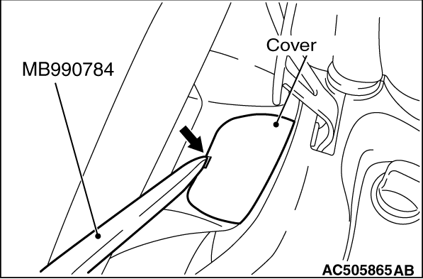
Insert the special tool ornament remover (MB990784) into the notch shown in the figure, and remove the cover.

<<B>> DRIVER’S AIR BAG MODULE CONNECTOR REMOVAL


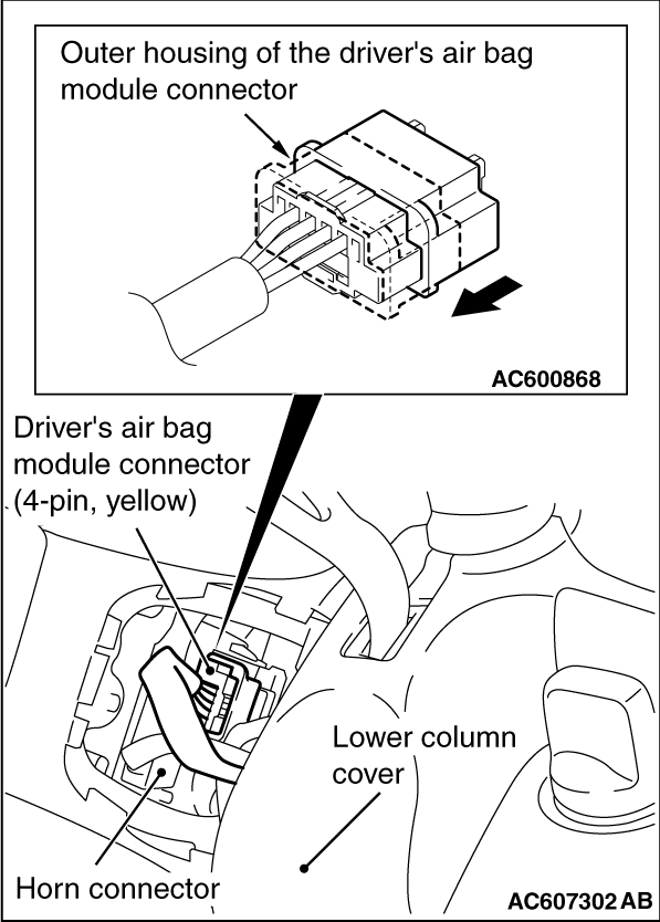
Slide the outer housing of the driver’s air bag module connector in the arrow direction shown, and disconnect the connector

<<C>> DRIVER’S AIR BAG MODULE REMOVAL


caution
  • Never use an electric tester to diagnose the air bag module circuit. Never attempt to disassemble the air bag module.
  • Be sure to store the removed air bag module in a clean and dry place with a pad surface facing upward.
  • When discarding the air bag module, discard after deploying the air bag as specified in the service procedure. (Refer to ).

<<D>> STEERING WHEEL ASSEMBLY REMOVAL


1.
caution 
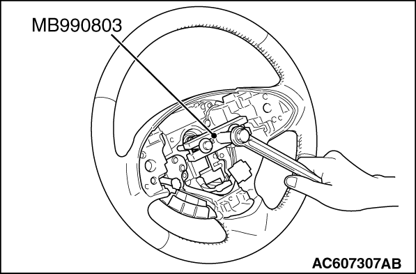
Use the special tool to remove the steering wheel since the steering column collision absorbing mechanism may be damaged.
Position the steering wheel in a straight ahead direction.

2.Using special tool steering wheel puller (MB990803), remove the steering wheel assembly as shown in the figure.

<<E>> CLOCK SPRING REMOVAL


caution The removed clock spring should be stored in a clean, dry place.

<<F>> PASSENGER’S (FRONT) AIR BAG MODULE CONNECTOR REMOVAL


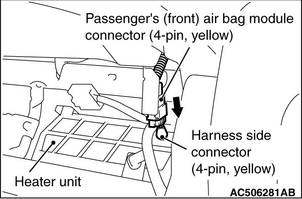
Disconnect the connector while sliding the wiring harness side connector part shown in the figure to the direction of the arrow.

<<G>> PASSENGER’S (FRONT) AIR BAG MODULE REMOVAL


caution
  • Never use an electric tester to diagnose the air bag module circuit. Never attempt to disassemble the air bag module.
  • The removed passenger’s air bag module should be stored in a clean, dry place with the deployment surface facing up.
  • When discarding the air bag module, discard after deploying the air bag as specified in the service procedure (Refer to ).

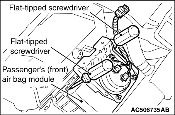
Insert a flat-tipped screwdriver or similar tool to the location shown in the figure. After disengaging the tabs, remove the passenger’s (front) air bag module.

INSTALLATION SERVICE POINTS


>>A<< PRE-INSTALLATION INSPECTION


1.Before the installation, check the air bag module and clock spring (Refer to ).
note Even when installing a new air bag module or clock spring, perform an inspection before the installation.
2.Connect the negative (-) battery terminal.
3.
caution Be sure to turn the ignition key to the LOCK (OFF) position when connecting or disconnecting M.U.T.-III.
Connect M.U.T.-III to the diagnosis connector (16 pin).
4.Turn the ignition switch to the ON position.
5.Read the diagnosis code, and check that everything is normal except the air bag module open circuit.
6.Turn the ignition switch to the LOCK (OFF) position.

>>B<< CLOCK SPRING INSTALLATION


1.Check that the front wheels are at the straight-ahead position.

2.
caution
  • If the centre of the clock spring is not correctly aligned, the steering wheel may not be turned fully or the cable inside the clock spring may be broken, causing the SRS airbag to be inoperative or operated incorrectly.
  • When aligning the clock spring neutral position mark, perform with the clock spring independently. If performed with the steering wheel sensor installed, the steering wheel sensor may be damaged.
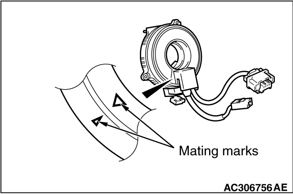
Align the mating marks of the clock spring.
<Alignment of mating marks>
(1) Turn the clock spring clockwise fully.
(2) Turn the clock spring anti-clockwise approximately three and 3/4 turns to align the mating marks.
(3) Install the clock spring to the column switch.

3.
caution Be sure to align the steering wheel sensor neutral position mark. If the neutral position marks are not aligned, the steering wheel operation may damage the steering wheel sensor.
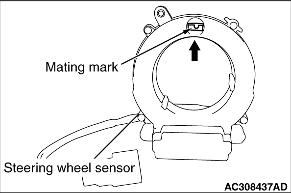
Align the steering wheel sensor neutral position mark. <Vehicle with ASC>
<Alignment of mating marks>
(1) When checking the neutral position check window of the steering wheel sensor, if an arrow can be seen, turn to the direction of the arrow, and align the neutral position mark as shown in the figure.
(2) Install the steering wheel sensor to the column switch assembly, maintaining the neutral position correctly.
(3) Install the column switch assembly to the vehicle, maintaining the neutral position correctly.

>>C<< STEERING WHEEL ASSEMBLY/AIR BAG MODULE INSTALLATION


1.
caution When installing the steering wheel assembly and air bag module, do not trap the clock spring harness.
After checking the clock spring centre alignment is already performed, install the steering wheel assembly and air bag module.
2.After the installation, check that there is no abnormality when the steering wheel is fully turned to left and right.

>>D<< DRIVER’S AIR BAG MODULE CONNECTOR/HORN CONNECTOR CONNECTION


Connect the connector securely and route the harnesses not to lie off the cover hole.

>>E<< POST-INSTALLATION CHECK


1.Connect the negative (-) battery cable.
2.Turn the ignition switch to the "ON" position.

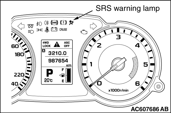
3.Check that the SRS warning lamp is illuminated for 6 to 8 seconds, and extinguished afterward.
4.If the lamp does not extinguish, perform the troubleshooting (Refer to ).