|
|
The battery power supply is supplied from the ignition switch (IG1) to SRS-ECU.
|
|
|
To SRS-ECU, the power is supplied from two independent battery power supplies (fuse No. 12 and 18) having fuses.
|
|
|
If the power is not supplied to SRS-ECU, the communication between M.U.T.-III and SRS-ECU cannot be established.
|
|
|
- Damaged wiring harness and connectors
- Battery failure
- Malfunction of the charging system
- Malfunction of SRS-ECU
|
|
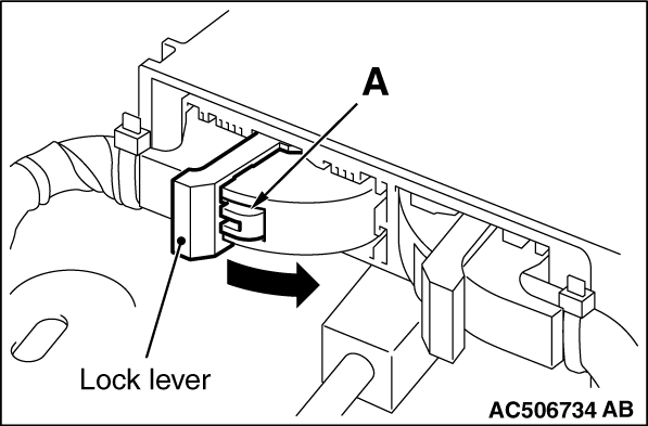
(1)While pushing the part "A" indicated in the figure of the harness side connector, turn the lock lever to the direction of the arrow to release the lock lever, and disconnect the C-31 SRS-ECU connectors.
(2)Take the measurements below at the C-31 wiring harness side connectors.
- Continuity between C-31 wiring harness side connector terminal No. 59 and body earth
OK: Continuity (less than 2 Ω)
Q.
Is the check result normal?
 Go to Step 2. Go to Step 2.
 Repair the wiring harness between the C-31 SRS-ECU connector terminal No. 59 and the earth. Repair the wiring harness between the C-31 SRS-ECU connector terminal No. 59 and the earth.
|
|
|
- Check the power supply line for open circuit.
|
|
|
Q.
Is the check result normal?
|
|
|
Repair the wiring harness.
|
|
|
|
|
|
Q.
Is the communication between M.U.T.-III and SRS-ECU possible?
|
|
|
Intermittent malfunction (Refer to GROUP 00 - How to Use Troubleshooting/Inspection Service Points - How to Cope with Intermittent Malfunction  ). ).
|
|
|
|
|
|
Replace SRS-ECU (Refer to ).
|
|
|
|
)
)
)
)
)
)