|
1.The headlamps should be aimed with the proper beam setting equipment, and in accordance with the equipment manufacture’s instructions.
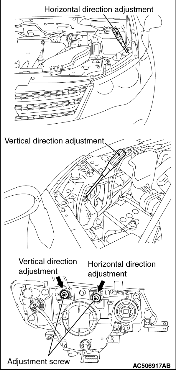
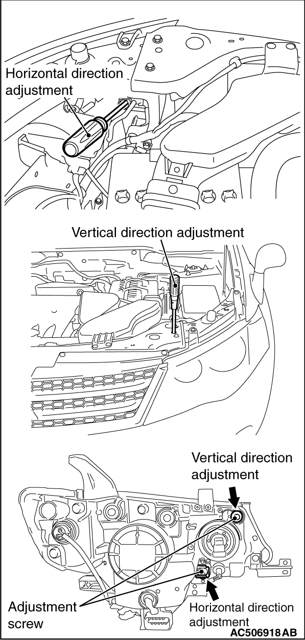
2.Alternately turn the adjusting screw to adjust the headlamp aiming.
|
|
|
1.Inspect for badly rusted or faulty headlamp assemblies.
|
|
|
2.These conditions must be corrected before a satisfactory adjustment can be made.
|
|
|
3.Inspect tyre inflation, and adjust if it is necessary.
|
|
|
4.If the fuel tank is not filled up, put weight in the luggage compartment to make up for the fuel shortage so that the weight will become 90%
of full-state weight or heavier. (0.8 kg per litter)
|
|
|
5.There should be no other load in the vehicle other than driver or substituted weight of approximately 75 kg placed in driver’s position.
|
|
|
6.Turn the headlamp levelling switch to the switch position "0." <Vehicles with headlamp manual levelling system>
|
|
|
7.Change the vehicle posture, and then operate the actuator of headlamp levelling unit once. <Vehicles with headlamp automatic levelling system>
|
|
|
8.Thoroughly clean the headlamp lenses.
|
|
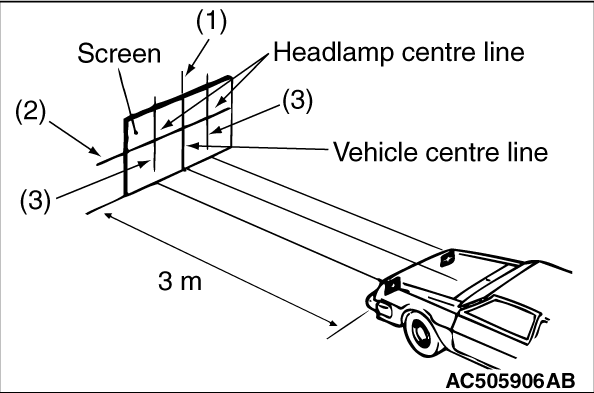
9.Place the vehicle on a level floor, perpendicular to a flat screen 3 m away from the bulb centre-marks on the headlamp lens.
10.Rock vehicle sideways to allow vehicle to assume its normal position.
11.To correct for distortion of the suspension, rock the bumpers on the front/rear side of the vehicle up and down three times alternately.
12.Run the engine at a speed of 2,000 r/min to charge the battery.
13.Four lines of adhesive tape (or equivalent markings) are required on screen or wall:
(1)
Position a vertical tape or mark so that it is aligned with the vehicle centre line.
(2)
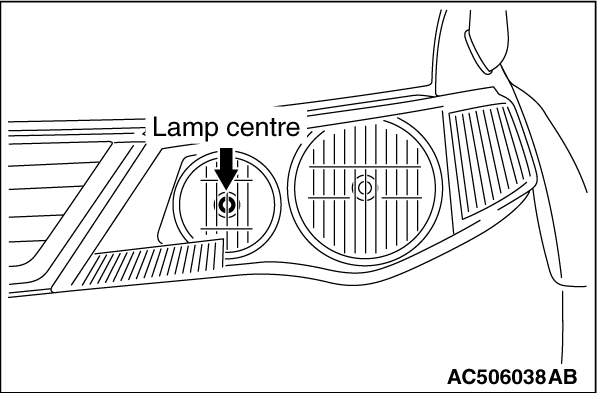
Measure the distance from the centre-marks on the headlamp lens to the floor. Transfer the measurement to the screen. Horizontal tape or mark on the screen is for reference of vertical adjustment.
|
|
| note |
Height from the floor to the centre of the headlamps (Reference value): 828 mm
|
|
(3)
Measure the distance from the centre line of the vehicle to the centre of each headlamp. Transfer the measurement to the screen. Vertical tape or mark on the screen with reference to the centre line of each headlamp bulb.
|
|
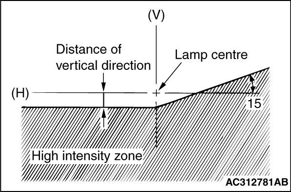
- The low-beam headlamp should project on the screen upper edge of the beam (cut-off).
- If not the case, turn the adjusting screws to achieve the specified low-beam cut-off location on the aiming screen.
|
|
Standard value:
Vertical direction;
36 mm (0.69°) below horizontal (H)
Horizontal direction;
15°
sloping section intersects the vertical line (V)
Limit:
Vertical direction;
Not within 21 mm (0.4°) below horizontal (H)
Horizontal direction;
±
26 mm (±
0.5°) from the vertical line
|
|
|
1.Inspect for badly rusted or faulty headlamp assemblies.
|
|
|
2.These conditions must be corrected before a satisfactory adjustment can be made.
|
|
|
3.Inspect tyre inflation, and adjust if it is necessary.
|
|
|
4.If the fuel tank is not filled up, put weight in the luggage compartment to make up for the fuel shortage so that the weight will become 90%
of full-state weight or heavier. (0.8 kg per litter)
|
|
|
5.There should be no other load in the vehicle other than driver or substituted weight of approximately 75 kg placed in driver’s position.
|
|
|
6.Thoroughly clean the headlamp lenses.
|
|
7.Place the vehicle on a level floor, perpendicular to a flat screen 3 m away from the bulb centre-marks on the headlamp lens.
8.Rock vehicle sideways to allow vehicle to assume its normal position.
9.To correct for distortion of the suspension, rock the bumpers on the front/rear side of the vehicle up and down three times alternately.
10.Run the engine at a speed of 2,000 r/min to charge the battery.
11.Four lines of adhesive tape (or equivalent markings) are required on screen or wall:
(1)
Position a vertical tape or mark so that it is aligned with the vehicle centre line.
(2)
Measure the distance from the centre-marks on the headlamp lens to the floor. Transfer the measurement to the screen. Horizontal tape or mark on the screen is for reference of vertical adjustment.
|
|
| note |
Height from the floor to the centre of the headlamps (Reference value): 828 mm
|
|
(3)
Measure the distance from the centre line of the vehicle to the centre of each headlamp. Transfer the measurement to the screen. Vertical tape or mark on the screen with reference to the centre line of each headlamp bulb.
|
|
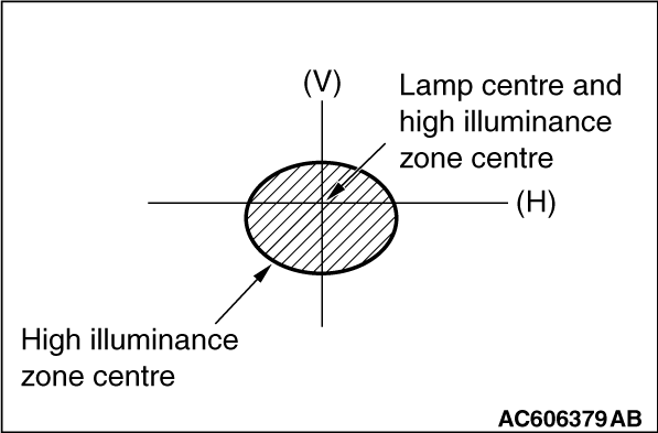
- Check that the high illuminance zone centre of the high-beam headlamp is at the high illuminance zone centre of the screen.
- If not the case, turn the adjusting screws to achieve the specified high-beam high illuminance zone location on the aiming screen.
|
|
Standard value:
Vertical direction and horizontal direction;
Intersecting position of vertical line (V) and horizontal line (H)
Limit:
Vertical direction;
26 mm (0.5°) or less below the horizontal (H)
Horizontal direction;
±26 mm (±0.5°) from the vertical line (V)
|
)
)
)
)
)
)
)
)