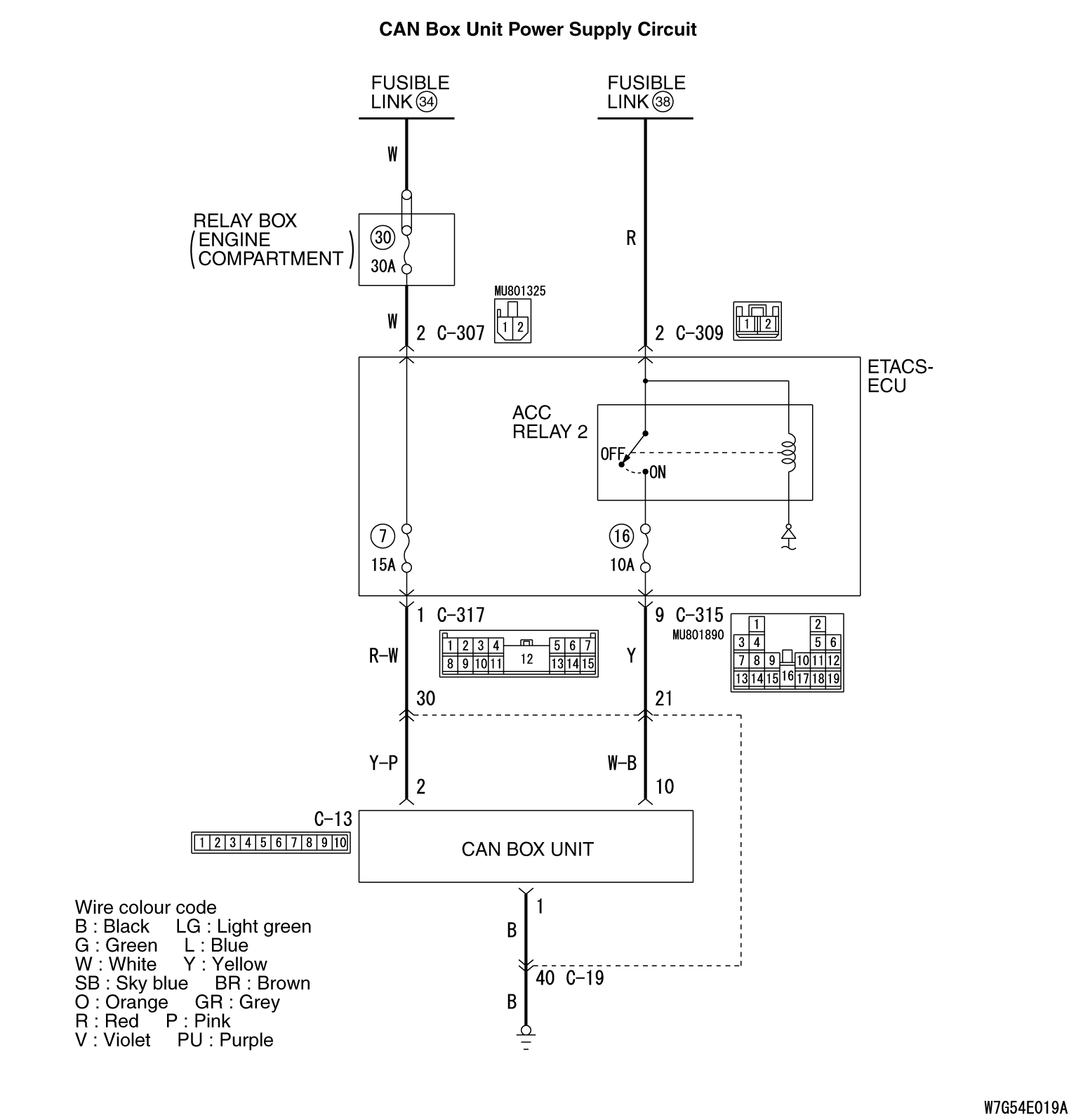
Inspection Procedure 11: Check the CAN box unit power supply circuit.
| caution |
Before replacing the ECU, ensure that the power supply circuit, the earth circuit and the communication circuit are normal.
|
TECHNICAL DESCRIPTION (COMMENT)
If the CAN box unit functions do not work at all, the CAN box unit power supply system, body earth system, or CAN box unit may have a problem.
PROBABLE CAUSES
- The wiring harness or connectors may have loose, corroded, or damaged terminals, or terminals pushed back in the connector
- The CAN box unit may be defective
|
|
STEP 1. Connector check: C-15 CAN box unit connector
|
|
|
Q.
Is the check result normal?
|
|
|
 Go to Step 2. Go to Step 2.
|
|
|
|
|
|
 Repair or replace the damaged component(s). Repair or replace the damaged component(s).
|
|
|
|
|
|
STEP 2. Resistance measurement at C-15 CAN box unit connector.
|
|
|
(1)Disconnect C-15 CAN box unit connector and measure the resistance available at the wiring harness side of the connector.
|
|
|
(2)Check the continuity between C-15 CAN box unit connector terminal No.1 and body earth.
OK: Continuity exists (2 ohms or less)
|
|
|
Q.
Is the check result normal?
|
|
|
Go to Step 4.
|
|
|
|
|
|
Go to Step 3.
|
|
|
|
|
|
STEP 3. Check the wiring harness between C-15 CAN box unit connector terminal No.1 and the body earth.
|
|
|
Q.
Is the check result normal?
|
|
|
No action is necessary and testing is complete.
|
|
|
|
|
|
Repair the wiring harness.
|
|
|
|
|
|
STEP 4. Voltage measurement at C-15 CAN box unit connector
|
|
|
(1)Disconnect CAN box unit connectors C-15 measure the voltage available at the wiring harness side of the connector.
|
|
|
(2)Measure the voltage between C-15 CAN box unit connector terminal No.2 and body earth.
OK: Battery positive voltage
|
|
|
Q.
Is the check result normal?
|
|
|
Go to Step 6.
|
|
|
|
|
|
Go to Step 5.
|
|
|
|
|
|
STEP 5. Check the wiring harness between C-15 CAN box unit connector terminal No.2 and fusible link (34).
|
|
|
| note |
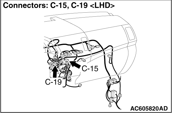
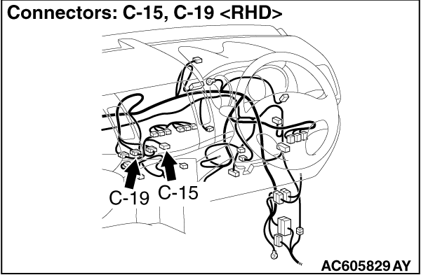
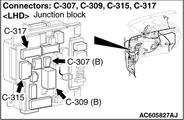
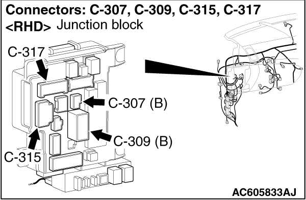
Prior to the wiring harness inspection, check intermediate connector C-19 and ETACS-ECU connectors C-307 and C-317, and repair if necessary.
|
|
|
|
Q.
Is the check result normal?
|
|
|
No action is necessary and testing is complete.
|
|
|
|
|
|
Repair the wiring harness.
|
|
|
|
|
|
STEP 6. Check the wiring harness between C-15 CAN box unit connector terminal No.10 and fusible link (38).
|
|
|
| note |
Prior to the wiring harness inspection, check intermediate connector C-19 and ETACS-ECU connectors C-309 and C-315, and repair if necessary.
|
|
|
|
Q.
Is the check result normal?
|
|
|
No action is necessary and testing is complete.
|
|
|
|
|
|
Repair the wiring harness.
|
|
|
|
)
)
)
)
)