|
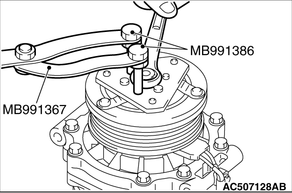
Use the special tools below to remove the self-locking nut.
- Special spanner (MB991367)
- Pin (MB991386)
|
|
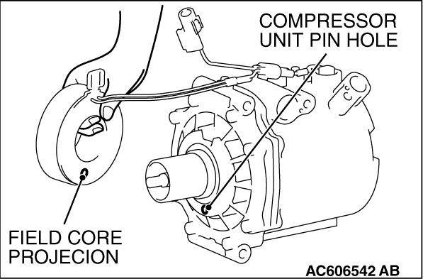
Install the A/C compressor coil while aligning the pin hole of A/C compressor
itself with the protrusion of A/C compressor coil
|
|
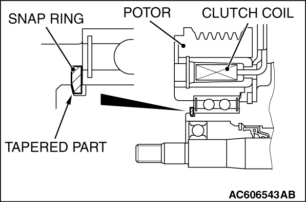
Use snap ring pliers to install the snap ring so that the taper faces outwards.
|
|
|
Use the special tool as during removal to secure the armature and tighten the self-locking
nut.
|
|
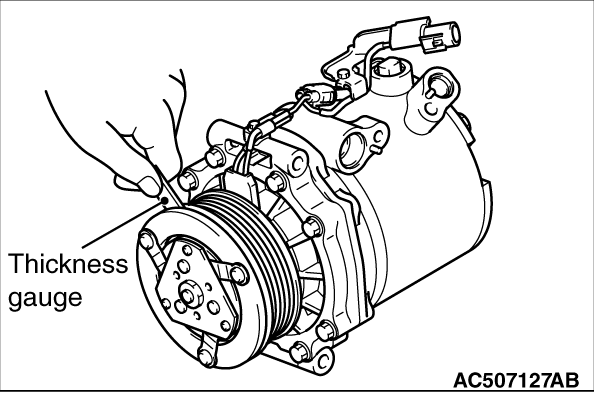
Check that the air gap of clutch satisfies the standard value. If not within the standard
value, use shims to adjust it.
Standard value: 0.3 -
0.5 mm
|
)

)
)
)
)